Hinet UPS User Manual
(12/01) Page 9
3.2 Setting standard Relay Card
The pre-settings required are only those which concern the interfaces wiring the external devices, i.e., personal
computer, safety switch, remote panel.
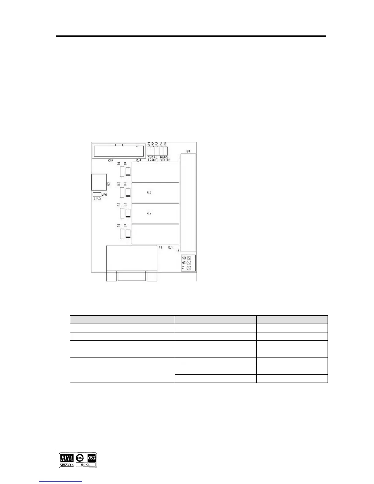
3.2.1 Setting options on the standard Relay Card
A standard Relay Card is situated on Hinet’s on the left side of the rear panel. This card is typically supplied and is
factory pre-set to operate with the PC.
When the operation is through the Remote Alarm Panel, the factory will deliver the card already preset to operate with
the cited panel.
A second card will be available on request on the right side of the rear panel.
Figure 3-2 Setting options on the standard Relay card
FUNCTION
JUMPER CLOSED JUMPER OPEN
Use With PC
JP4 JP5
Use With Remote Panel
JP5 JP4
EPO Enabled
- JP6
EPO Disabled
JP6 -
JP1 -
Serial Communication
JP2 -
JP3 -




 To Next Page