Netlink Installation and Operation Manual
36 37
Installation and Operation
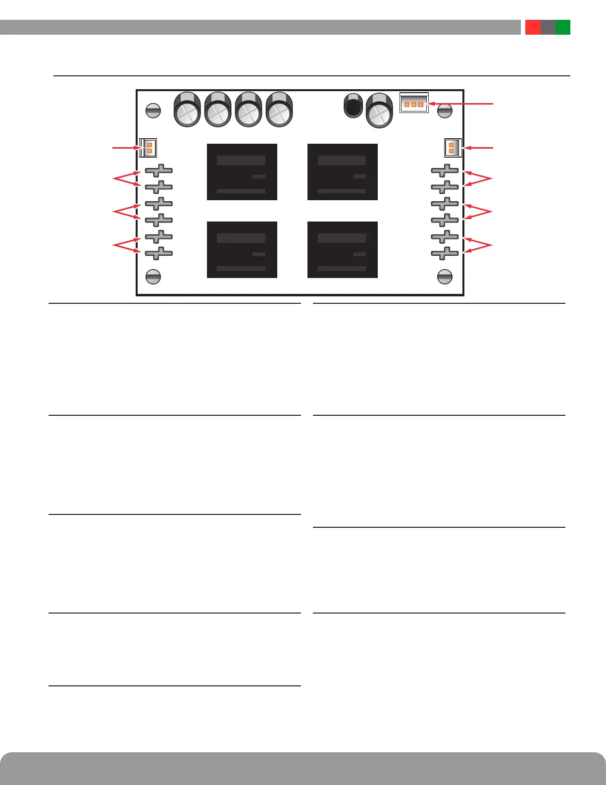
A2.2 NS2 Module Overview
19 NS2 - ADC Output (ADC1 & ADC2)
This connector provides voltage outputs for measure-
ment by the Netlink board, indicating presence of volt-
age on SB1-1 and SB1-2. Using the supplied cable, this
connects to the ADC Input of the Netlink board (J15).
The voltages indicated are not accurate and are only for
indication of presence of voltage. Place jumper J9 on
the Netlink board ON when using this output.
20 NS2 - Buss Inputs - Power Source 1 (B1-1 & B2-1)
These faston connectors are the B1 and B2 power in-
puts to the NS2 for power source #1. Typically, in a
LifeSafety Power FPA system, this would be the blue
and orange wires from Transformer #1. The power re-
turn (brown wire in an FPA System) connects to the
BR1 faston - See #20.
21 NS2 - Buss Inputs - Power Source 2 (B1-2 & B2-2)
These faston connectors are the B1 and B2 power in-
puts to the NS2 for power source #2. Typically, in a
LifeSafety Power FPA system, this would be the blue
and orange wires from Transformer #2. The power re-
turn (brown wire in an FPA System) connects to the
BR2 faston - See #20.
22 NS2 - Buss Inputs - Power Returns (BR1 & BR 2)
These are the power returns for the Buss Inputs. See #18
and #19. Typically, in a LifeSafety Power FPA system,
these would connect to the brown secondary wires of the
transformers.
23 NS2 - Buss Outputs - Power Returns (SBR1 & SBR2)
These are the switched power returns out to the BR
terminals of the A8 distribution boards in a LifeSafety
Power FPA system.
24 NS2 - Buss Outputs - Power Source 2 (SB1-2 & SB2-2)
These are the switched B1 and B2 outputs from pow-
er source 2. When the control output #2 of the Netlink
board is activated, power will be removed from these
outputs. Typically, these are connected to the B1 and B2
inputs of the A8 distribution boards in a LifeSafety power
FPA system. The BR of the A8 connects to the SBR2 fas-
ton - See #21.
25 NS2 - Buss Outputs - Power Source 1 (SB1-1 & SB2-1)
These are the switched B1 and B2 outputs from pow-
er source 1. When the control output #1 of the Netlink
board is activated, power will be removed from these
outputs. Typically, these are connected to the B1 and B2
inputs of the A8 distribution boards in a LifeSafety power
FPA system. The BR of the A8 connects to the SBR1 fas-
ton - See #21.
26 NS2 - Control Inputs (J9)
This is the control input from the Netlink board, allow-
ing control of the power to the outputs via the Netlink's
web interface. Using the cable with two 2-pin plugs,
connect between this connector and J10 on the Netlink
board - See #13 in Section 1.2.
27 NS2 - Netlink Power Output (+12V-)
This is the power output for powering the Netlink board
in an AC-only system. The NS2 converts AC power from
the buss inputs to regulated DC power for the Netlink
board. Using the supplied cable, connect this connec-
tor to the V+/V- input of the Netlink.

 Loading...