FlexPower DC Power System Installation Manual
6 7
Installation and Operation
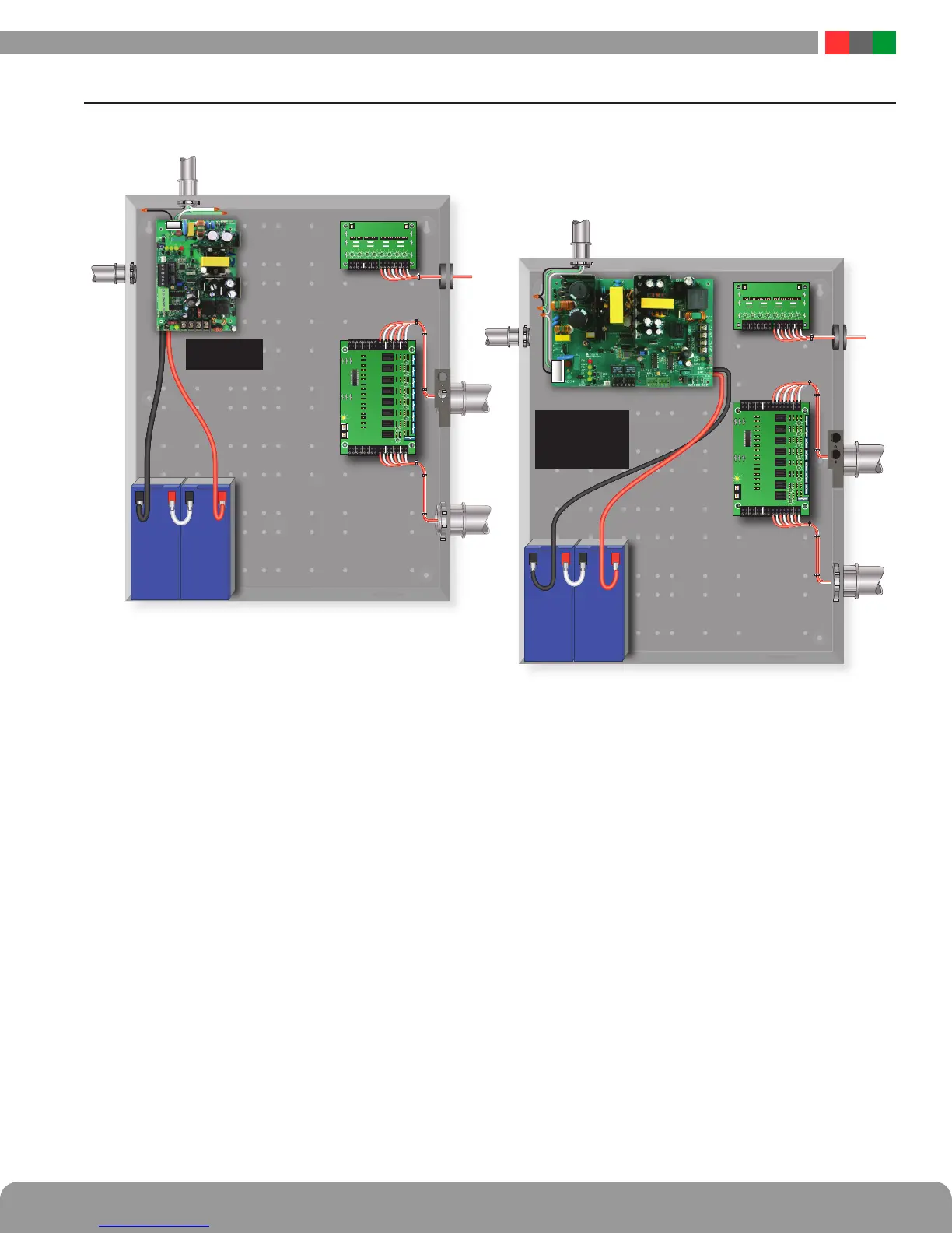
1.4 Typical Installation & Wire Routing
The drawing above shows a typical installation.
Actual configuration and wire routing will vary based on
the components installed in your system.
The following guidelines should be followed for installation:
• Class 2 Power limited wiring must be separated from
non-power limited wiring by a minimum of 1/4 inch and
must use separate knockouts.
• The installation and all wiring methods shall be in accor-
dance with ANSI/NFPA70 and all local codes.
• The installation and all wiring methods shall be in accor-
dance with ANSI/NFPA70 and all local codes. For ULC
S527 compliance, installation and all wiring methods shall
be in accordance with the Canadian Electrical Code, C22.1,
Part I, Section 32.
• Any wiring passing through knockouts in the bottom or
top surfaces of the enclosure must be enclosed in rigid
or flexible metal conduit.
• For Canadian Installations - For permanently connected
equipment, a readily accessible disconnect device shall be
incorporated external to the equipment. Output circuits
not connected to removable terminal strips shall also
utilize a readily accessible disconnect device.
AC Input Wiring
AC Input Wiring
Class
2
Class
2
FPO75
FPO150
FPO250
 Loading...
