FlexPower DC Power System Installation Manual
14 15
User Certificate
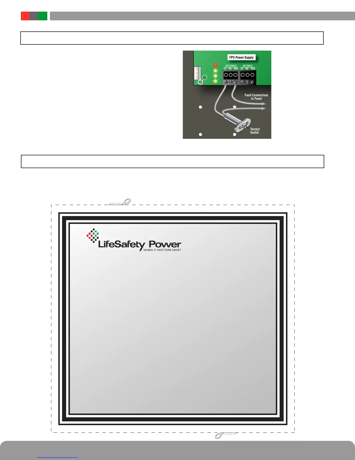
Appendix 1 – Tamper Switch Wiring
All FlexPower DC systems with an enclosure include a normally
closed tamper switch for monitoring by the host panel. The
tamper switch can either be brought into a dedicated input in
the panel (see the panel's instructions), to the Event 1 input of a
Netlink Network Module (See the Netlink's Instruction Manual),
or the tamper switch may be series connected into the System
Fault relay in the FPO supply as shown in the illustration.
Any UL1076 installation must use the tamper switch to indicate
the opening or removal of the front door of the enclosure.
Below is a certificate required for UL603 installations, to be cut out, framed and hung adjacent to the FlexPower
Power Supply system after installation. It contains the required battery information, as specified in UL603.
Specifications for the following model numbers:
FPO150 / FPO250
Maximum Charging Current: 2A
Maximum Battery Capacity: 80AH
Battery Type: Sealed Lead Acid or Gel Cell
Specifications for the following model numbers:
FPO75
Maximum Charging Current: 1A
Maximum Battery Capacity: 40AH
Battery Type: Sealed Lead Acid or Gel Cell
Appendix 2 – User Certificate
 Loading...
