FlexPower DC Power System Installation Manual
iv 1
Installation and Operation
Mounting an Enclosure
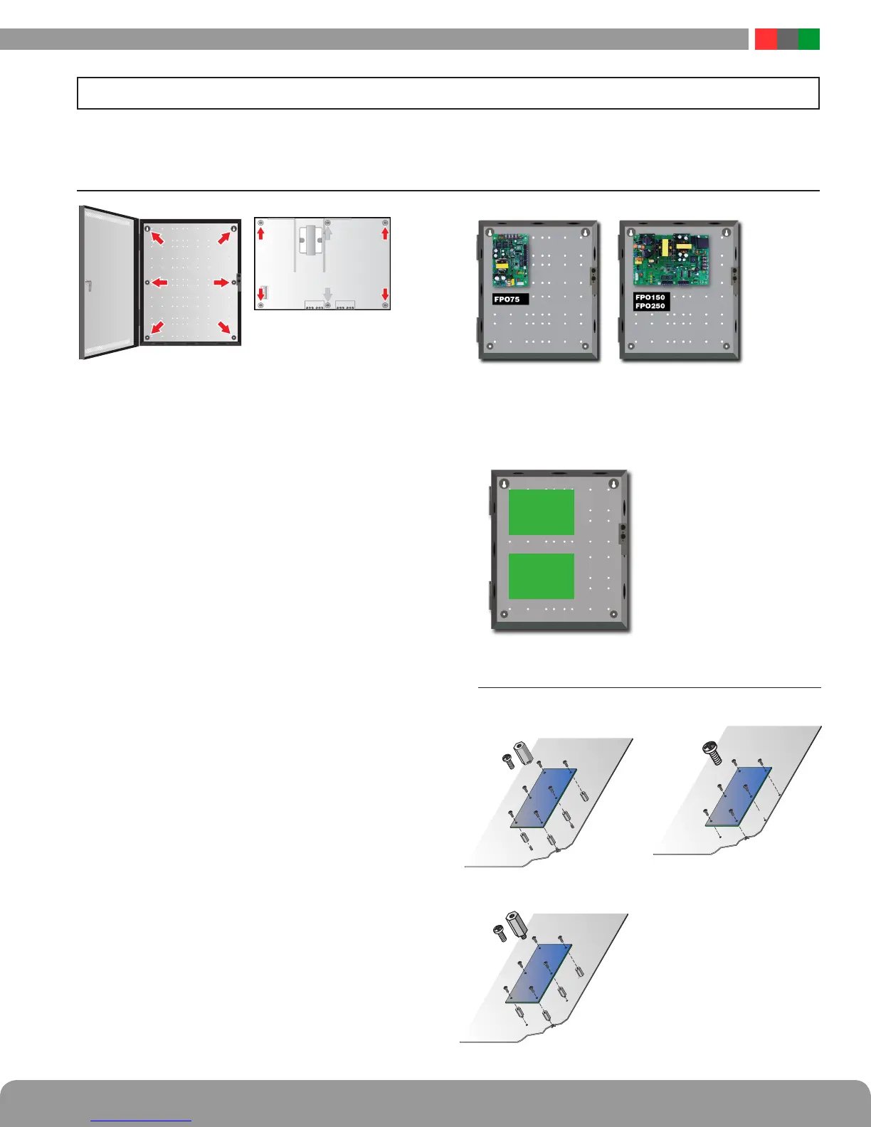
Use the following procedure when mounting a wall-mount enclosure
(figure 1).
1. (Optional) Remove the enclosure’s cover.
2. Locate the top keyhole mounting holes in the back of the enclosure.
3. Mark and pre-drill the locations for the keyholes in the mount-
ing surface.
4. Partially install two fasteners appropriate for the surface on
which the enclosure is being installed. Leave the heads of the
fasteners approximately ¼" out from the surface. Minimum
fastener size should be #10 or larger.
5. Hang the enclosure on the two fasteners and mark the loca-
tions of the remaining mounting holes.
6. Remove the enclosure and pre-drill the locations for the re-
maining mounting holes.
7. Re-hang the enclosure on the top mounting fasteners, start
the remaining fasteners and tighten all fasteners.
8. Reinstall the enclosure’s cover, if removed in step 1.
i It is the installer’s responsibility to determine the ap-
propriate fastening system for use with the surface the
enclosure is being mounted to.
i For UL1076 applications, after installation is complete, the
installer must install the two supplied 1" long screws to the
edge of the enclosure's cover for additional security.
Mounting an FPO PS Board to an Enclosure
Use the following procedure when mounting an FPO power sup-
ply to a LifeSafety Power enclosure (figure 2).
1. Locate the appropriate mounting holes in the enclosure and
snap the four or six standoffs provided into the holes.
2. Align the board mounting holes (mounting hole locations are
indicated in the drawing above) with the standoffs and snap the
board onto the standoffs. Be sure the board is properly oriented
before snapping the board onto the standoffs (Figure 3).
3. When two FPO/FPV boards are installed, the larger shall be
located on top (figure 4).
Mounting a Sub Assembly to an Enclosure
Third Party sub assemblies will be mounted in one of three methods
based on the supplied mounting hardware (figure 5).
1.1 Mounting
The following pages cover the installation, setup, and basic operation of the FPO series power supplies.
Section 1 – Installation and Operation
FPO/FPV
smaller
FPO/FPV
larger
Figure 1 Figure 2 Figure 3
Figure 5
Figure 4
Screw
Female to female Stando
Screw
Male to female Stando
Screw mounting
 Loading...
