FlexPower DC Power System Installation Manual
4 5
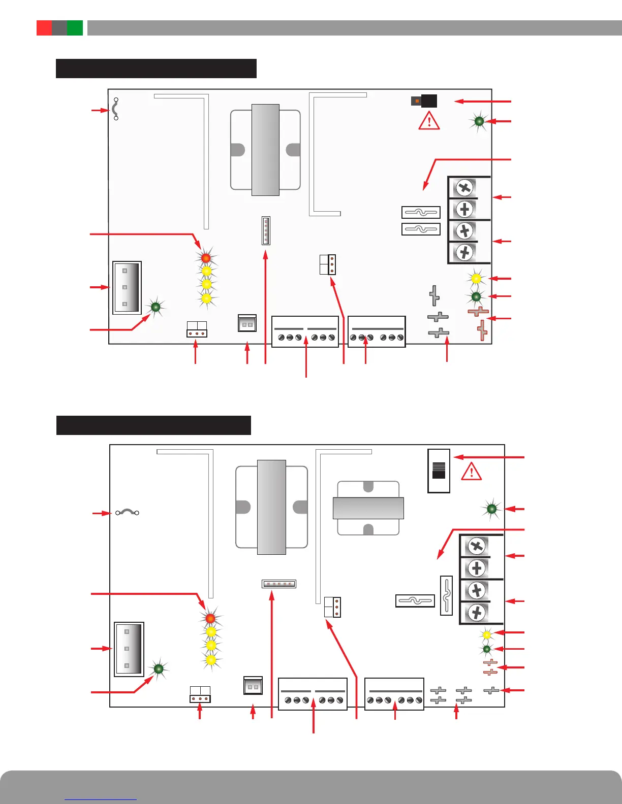
Installation and Operation
FAI INPUTFAI INPUTSYS FLTSYS FLT
AC FLTAC FLT
BRBR
DC1DC1
V+V+
V-V-
DC2DC2
DataLinkDataLink
+ DC2 –+ DC2 – + DC1 –+ DC1 –
AC Input
Flex IO
Earth
GND DET
Battery
Detect
Battery
Detect
120/230VAC
Cut for 230VCut for 230V
DC2 NCDC2 NC
DC2 NODC2 NO
DC1
DC2
AC ON
REV BAT
GND FLT
AC FLT
FAI
SYS FLT
12V
24V
BB
+
BB
–
2
1
Observe battery polarity
or damage may result
Observe battery polarity
or damage may result
i
FPO150 / 250
For UL compliance, the AC fault contact
must be monitored by a Listed control panel
2
1
FAI INPUTFAI INPUTSYS FLTSYS FLT
AC FLTAC FLT
12V
24V
Observe battery polarity
or damage may result
Observe battery polarity
or damage may result
i
+ DC2 –+ DC2 – + DC1 –+ DC1 –
AC Input
Flex IO
120/230VAC
Cut for 230VCut for 230V
DC2 NCDC2 NC
DC2 NODC2 NO
FPO75
AC ON
DC2
DC1
REV BAT
GND FLT
AC FLT
FAI
SYS FLT
DataLinkDataLink
BB
+
BB
–
BRBR
DC1DC1
DC2DC2
For UL compliance, the AC fault contact
must be monitored by a Listed control panel
Earth
GND DET
2
1
Battery
Detect
Battery
Detect
2
1
 Loading...
