39
q
LS_Norm
=
·
Q
burner
A
v
· v(t) · ρ
AIR
· c
pl
· (ϑ
L
(t) — ϑ
U
)
273 + ϑ
outside ACTUAL
273 + ϑ
outside REF
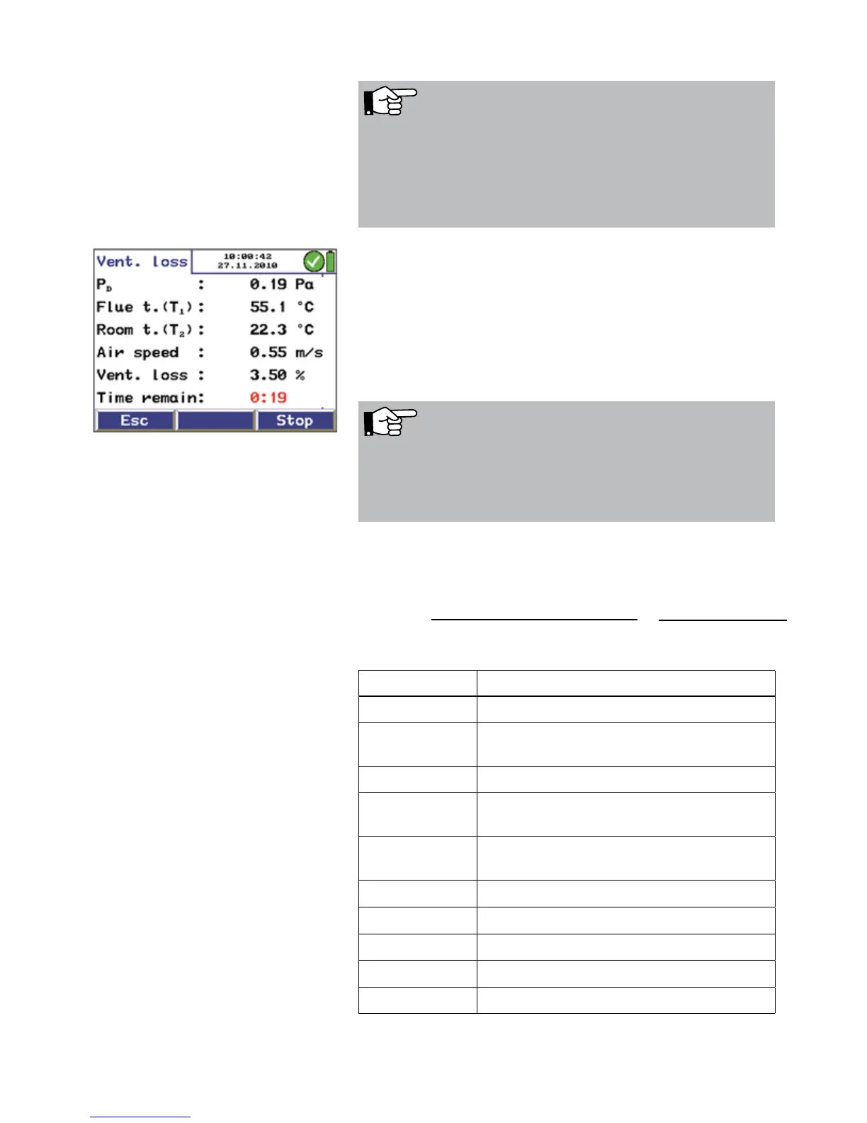
The measurement will be done automatically.
• When the burner is turned off, press "Start" to start the
measurement.
After 30 seconds, the data recording will start automati-
cally. The captured values are shown in the display.
• Press "OK" to capture the calculated ventilation loss.
NOTE!
The S-tube must be adjusted before the measurement pro-
cedure starts, since it is required to check and/or adjust the
oppositely running orientation of the measuring tubes after
loosening the knurled screws and adjusting the immersion
depth
Fig. 49: Measuring the ventilation loss
NOTE!
The wanted signal of the S-tube probe is better than that of
a normal pitot tube, if the flow speed is equal. In the setup-
menu the pitot factor 0.93 must be set once.
The measured values are converted according to the follow-
ing formula:
Description Data
q
LS_Norm
Ventilation loss in %
A
v
Area cross section of the flue gas pipe
in m²
v(t) Air velocity in the flue gas pipe in m/s
r
AIR
air density, temperature compensated,
e.g. 20 °C 1,2 kg/m³
c
pl
specific heat capacity, norm:
0,279 Wh/kg °C
J
L
air temperature in the exhaust stack
J
U
air temperature in ° in the fireplace room
J
outside ACTUAL
Outside temperature, actual value in °C
J
outside REF
Outside reference tem-perature, 15 °C
Q
burner
Nominal power of the heat generator
The conversion rule for the determination of the flue gas loss
is integrated in the meter's program.