5/76
EN
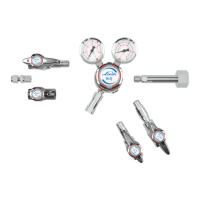
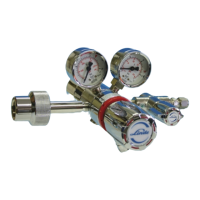
Single and dual stage cylinder regulator with metal diaphragm and 6 ports.
Created and approved as ISO7291, including oxygen test, (see table chapter 1.2).
This cylinder regulator consists of regulator body, inlet and outlet gauge, cylinder connection and pressure
relief valve. It is available with several outlet connections and/ or several additional components:
• Shut o valve at outlet (A)
• Regulating valve at outlet (B)
• Purge valve at inlet (P)
• Purge Valve at outlet (DP)
• Inert gas purge valve at inlet (TP)
• Inert gas purge valve at inlet and shut o valve at outlet (TPA), only with stainless steel version
• Inert gas purge valve at inlet and regulating valve at outlet (TPB), only with stainless steel version
• Triple purge block at inlet (EP), only with stainless steel version
• Triple purge block at inlet and shut of valve at outlet (EPA), only with stainless steel version
• Triple purge block at inlet and regulating valve at outlet (EPB), only with stainless steel version
The versions C200/1 TP, C200/1 TPA, C200/1 TPB, C200/2 TP, C200/2 TPA and C200/2 TPB allow purging
of regulator with purge gas. The versions C200/1 EP, C200/1 EPA and C200/ EPB allow purging of regulator
with triple purge block. These versions are especially suitable for corrosive and toxic gases.
Cylinder regulator with triple purge block enables the drying of the regulator and the removing of moist at-
mospheric air, which came inside the regulator before initial startup or at gas cylinder. The triple purge block
version enables also the purging of the regulator to clean it from toxic, corrosive or self-igniting gases before
taking out of operation.
1.3. EXPLANATION OF SYMBOLS
SAFETY INFORMATION
Safety information is highlighted by symbols in these instruc-
tions. This safety information is preceded by signal words that
define the extent of risk.
DANGER!
This combination of symbol and signal word indicates
an immediately dangerous situation that will cause death or
severe injury if not avoided.
WARNING!
This combination of symbol and signal word indicates
a possibly dangerous situation that can cause death or severe
injury if not avoided.
BEWARE!
This combination of symbol and signal word indicates
a possibly dangerous situation that can cause minor injury if
not avoided.
NOTE!
This combination of symbol and signal word indicates
a possibly dangerous situation that can cause property and
environmental damage if not avoided.
TIPS AND RECOMMENDATIONS
This symbol highlights useful tips and recommendations,
together with help for ensuring ecient and trouble-free op-
eration.
SPECIAL SAFETY
INFORMATION
The following symbols are used in the safety information
to draw your attention to particular risks.
DANGER!
This combination of symbol and signal word indicates an im-
mediately dangerous situation involving electrical current. Ig-
noring such a warning could result in severe or fatal injuries.