Induktive
Leitlinienführung
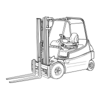
Systembeschreibung
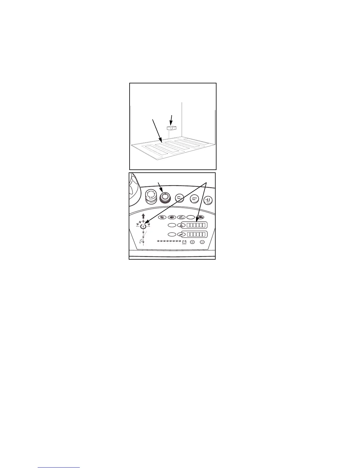
Ein Frequenzgenerator (1) speist einen im
Boden verlegten Draht (2) mit Wechsel-
strom. Dieser Wechselstrom wird von
Antennen, die im Fahrzeug eingebaut
sind, als Signal registriert und zur Führung
des Fahrzeuges verwertet.
Ein Computer steuert nach Auswertung
der Signale das Fahrzeug entlang der
Drahtnut. Umfangreiche Sicherheitsschal-
tungen und ein Diagnoseprogramm ver-
einfachen die Servicearbeit am System.
Im Bedienpult ist die Bedieneinheit für die
induktive Lenkregelung installiert. Auf der
Bedieneinheit (3) wird der jeweils aktuelle
Betriebszustand des Systems angezeigt.
Im Fehlerfalle wird mit Laufschrift der
jeweilige Fehler beschrieben.
Nach Einschalten der Steuerung läuft im
Lenkregelungssystem ein Selbsttest ab.
Schalter (4) im dem Bedienpult dient zur
Umschaltung von Handfahrt auf Automa-
tikfahrt.
Inductive wire
guidance
Description of system
A frequency generator (1) feeds a wire (2),
which is layed in the floor, with AC. This
AC is recorded by sensors, which are
installed in the truck, and is used to guide
the truck.
After having evaluted the signal, a compu-
ter steers the truck along the wire. Exten-
sive safety circuits and a diagnosis pro-
gram simplify the service work at the
system.
The operating panel for the inductive stee-
ring control is installed in the operation
area of the driver. The actual operating
condition of the system is indicated on the
operating panel (3). Any error is shown by
means of a display with running letters.
After the control has been switched on, a
selftest in the steering control system is
triggered.
Switch (4) in the control desk is used to
switch over between manual and automa-
tic travel.
60 K10, K13