LTC2983
25
2983fc
For more information www.linear.com/LTC2983
(4) Diode Ideality Factor
The last field in the channel assignment word (B21 to B0)
sets the diode ideality factor within the range 0 to 4 with
1/1048576 (2
–20
) resolution. The top two bits (B21 to B20)
are the integer part and bits B19 to B0 are the fractional
part of the ideality factor (see Table 20).
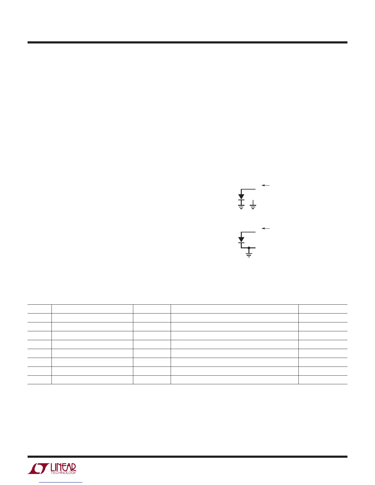
Diode channel assignments follow the general convention
shown in Figure 5. The anode ties to CH
D
(where D is
the selected channel number) for both the single-ended
and differential modes of operation, and the cathode is
grounded. For differential diode measurements, the cathode
is also tied to CH
D-1
.
Fault Reporting - Diode
Each sensor type has unique fault reporting mechanism
indicated in the upper byte of the data output word.
Table 21 shows faults reported in the measurement of
diodes.
Bit D31 indicates the diode is open, shorted, not plugged
in, wired backwards, or the ADC reading is bad. Any of
these are hard faults and –999°C or °F is reported. Bit
D30 indicates a bad ADC reading. This can be a result of
either a broken (open) sensor or an excessive noise event
(ESD or static discharge into the sensor path). This is a
APPLICATIONS INFORMATION
Figure 5. Diode Channel Assignment Convention
hard error and –999°C or °F is reported. In the case of
an excessive noise event, the device should recover and
the following conversions will be valid if the noise event
was a random, infrequent event. Bits D29 and D28 are not
used for diodes. Bits D27 and D26 indicate over or under
temperature limits (defined as T > 130°C or T < –60°C). The
calculated temperature is reported, but the accuracy may
be compromised. Bit D25 indicates the absolute voltage
measured by the ADC is beyond its normal operating range.
If a diode is used as the cold junction element, any hard
or soft error is flagged in the corresponding thermocouple
result (bits D28 and D29 in Table 15).
Table 21. Diode Fault Reporting
BIT FAULT ERROR TYPE DESCRIPTION OUTPUT RESULT
D31 Sensor Hard Fault Hard Open, Short, Reversed, or Hard ADC –999°C or °F
D30 Hard ADC-Out-of-Range Hard Bad ADC Reading (Could Be Large External Noise Event) –999°C or °F
D29 Not Used for Diodes N/A Always 0
D28 Not Used for Diodes N/A Always 0
D27 Sensor Over Range Soft T > 130°C Suspect Reading
D26 Sensor Under Range Soft T < –60°C Suspect Reading
D25 ADC Out-of-Range Soft ADC Absolute Input Voltage Is Beyond ±1.125 • V
REF
/2 Suspect Reading
D24 Valid NA Result Valid (Should Be 1) Discard Results if 0 Valid Reading
2983 F05
SINGLE-ENDED
= CH
D
(1≤ D ≤ 20)
COM
CH
D
CHANNEL
ASSIGNMENT
DIFFERENTIAL
= CH
D
(2≤ D ≤ 20)
CH
D
CH
D-1
CHANNEL
ASSIGNMENT