LTC2983
55
2983fc
For more information www.linear.com/LTC2983
SUPPLEMENTAL INFORMATION
2983 F33
CH
ADC
SINGLE-ENDED
CHANNEL
ASSIGNMENT
= CH
ADC
(1 ≤ ADC ≤ 20)
= CH
ADC
(2 ≤ ADC ≤ 20)
24-BIT
∆∑ ADC
24-BIT
∆∑ ADC
CHANNEL
ASSIGNMENT
DIFFERENTIAL
COM
CH
ADC
CH
ADC-1
–
+
–
+
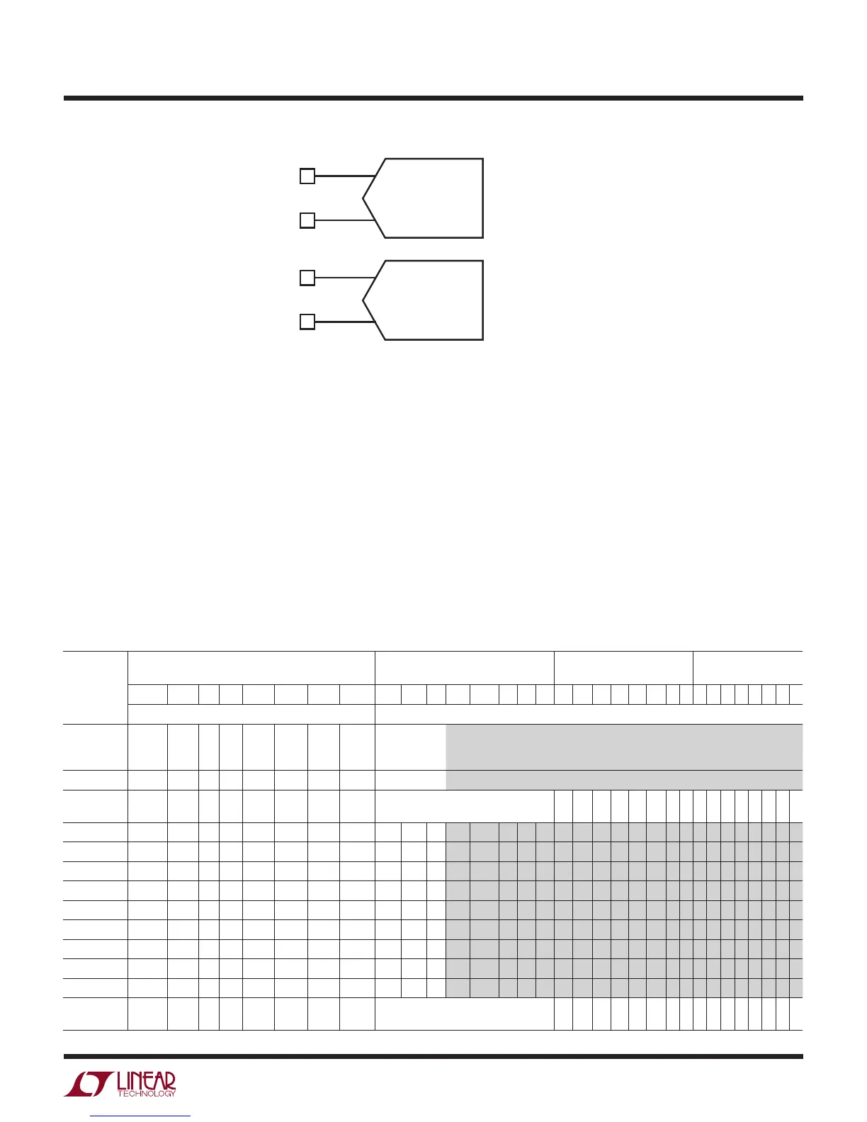
Figure 33. Direct ADC Channel Assignment Conventions
Table 63. Direct ADC Output Format
START ADDRESS START ADDRESS + 1 START ADDRESS + 2 START ADDRESS + 3
(END ADDRESS)
D31 D30 D29 D28 D27 D26 D25 D24 D23 D22 D21 D20 D19 D18 D17 D16 D15 D14 D13 D12 D11 D10 D9 D8 D7 D6 D5 D4 D3 D2 D1 D0
Fault Data SIGN MSB LSB
Volts Sensor
Hard
Fault
Range
Hard
Fault
NA NA Soft
Above
Soft
Below
Soft
Range
Valid
Always
1 ± 2V 1V 0.5V 0.25V ...
Integer Fraction
>V
REF
1 1 0 0 1 0 1 CLAMPED to Factory Programmed Value
of V
REF
1.75 • V
REF
/2 1 1 0 0 1 0 1 1 0 1 0 0 0 1 1 0 0 0 0 0 0 0 0 0 0 0 0 0 0 0 0 0
1.125 •
V
REF
/2 0 0 0 0 1 0 1 1 0 0 1 0 1 1 0 1 0 0 0 0 0 0 0 0 0 0 0 0 0 0 0 0
V
REF
/2 0 0 0 0 0 0 0 1 0 0 1 0 1 0 0 0 0 0 0 0 0 0 0 0 0 0 0 0 0 0 0 0
V
REF
/2
22
0 0 0 0 0 0 0 1 0 0 0 0 0 0 0 0 0 0 0 0 0 0 0 0 0 0 0 0 0 0 0 1
0 0 0 0 0 0 0 0 1 0 0 0 0 0 0 0 0 0 0 0 0 0 0 0 0 0 0
0 0 0 0 0 0
–V
REF
/2
22
0 0 0 0 0 0 0 1 1 1 1 1 1 1 1 1 1 1 1 1 1 1 1 1 1 1 1 1 1 1 1 1
–V
REF
/2 0 0 0 0 0 0 0 1 1 1 0 1 1 0 0 0 0 0 0 0 0 0 0 0 0 0 0 0 0 0 0 0
–1.125 • V
REF
0 0 0 0 0 1 1 1 1 1 0 1 0 0 1 1 0 0 0 0 0 0 0 0 0 0 0 0 0 0 0 0
–1.75 • V
REF
1 1 0 0 0 1 1 1 1 0 1 1 1 0 1 0 0 0 0 0 0 0 0 0 0 0 0 0 0 0 0 0
< –V
REF
1 1 0 0 0 1 1 1 CLAMPED to Factory Programmed Value
of –V
REF
Direct ADC Measurements
In addition to measuring temperature sensors, the LTC2983
can perform direct voltage measurements. Any channel
can be configured to perform direct single-ended or dif-
ferential measurements. Direct ADC channel assignments
follow the general convention shown in Figure 33. The
32-bit channel assignment word is programmed into a
memory location corresponding to the input channel.
The channel assignment word is 0xF000 0000 for differ-
ential readings and 0xF400 0000 for single-ended. The
positive input channel ties to CH
ADC
for both single-ended
and differential modes. For single-ended measurements
the ADC negative input is COM while for differential mea-
surements it is CH
ADC-1
. For single ended measurements,
COM can be driven with any voltage above GND–50mV
and below V
DD
–0.3V.
The direct ADC results are available in memory at a
location corresponding to the conversion channel.