LTC2983
24
2983fc
For more information www.linear.com/LTC2983
Table 18. Diode Sensor Selection
(1) SENSOR TYPE
B31 B30 B29 B28 B27 SENSOR TYPE
1 1 1 0 0 Diode
Table 19. Diode Excitation Current Selection
(3) EXCITATION CURRENT
B23 B22 1I 4I 8I
0 0 10µA 40µA 80µA
0 1 20µA 80µA 160µA
1 0 40µA 160µA 320µA
1 1 80µA 320µA 640µA
DIODE MEASUREMENTS
Table 20. Programming Diode Ideality Factor
(4) DIODE IDEALITY FACTOR VALUE
B21 B20 B19 B18 B17 B16 B15 B14 B13 B12 B11 B10 B9 B8 B7 B6 B5 B4 B3 B2 B1 B0
Example h 2
1
2
0
2
–1
2
–2
2
–3
2
–4
2
–5
2
–6
2
–7
2
–8
2
–9
2
–10
2
–11
2
–12
2
–13
2
–14
2
–15
2
–16
2
–17
2
–18
2
–19
2
–20
1.25 0 1 0 1 0 0 0 0 0 0 0 0 0 0 0 0 0 0 0 0 0 0
1.003 (Default) 0 0 0 0 0 0 0 0 0 0 0 0 0 0 0 0 0 0 0 0
0 0
1.006 0 1 0 0 0 0 0 0 0 1 1 0 0 0 1 0 0 1 0 0 1 1
Bit B24 enables a running average of the diode temperature
reading. This reduces the noise when the diode is used
as a cold junction temperature element on an isothermal
block where temperatures change slowly.
The algorithm used for diode averaging is a simple recursive
running average. The new value is equal to the average of
the current reading plus the previous value.
NEW VALUE =
CURRENT READING
+
PREVIOUS VALUE
If the current reading is 2°C above or below the previous
value, the new value is reset to the current reading.
(3) Excitation Current
The next field in the channel assignment word (B23 to B22)
controls the magnitude of the excitation current applied to the
diode (see Table 19). In the two conversion cycle mode, the
device performs the first conversion at a current equal to 8x
the excitation current 1I. The second conversion occurs at 1I.
Alternatively, in the three conversion cycle mode the first
conversion excitation current is 8I, the second is 4I and
the 3rd is 1I.
APPLICATIONS INFORMATION
(2) Sensor Configuration
The sensor configuration field (bits B26 to B24) is used to
define various diode measurement properties. Configura-
tion bit B26 is set high for single-ended (measurement
relative to COM) and low for differential.
Bit B25 sets the measurement algorithm. If B25 is low, two
conversion cycles (one at 1I and one at 8I current excitation)
are used to measure the diode. This is used in applications
where parasitic resistance between the LTC2983 and the
diode is small. Parasitic resistance effects can be removed
by setting bit B25 high, enabling three conversion cycles
(one at 1I, one at 4I and one at 8I).
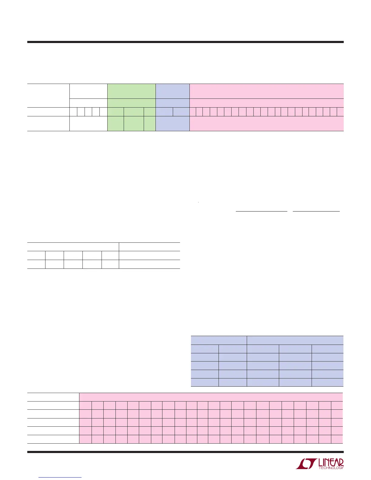
Table 17. Diode Channel Assignment Word
(1) SENSOR TYPE (2) SENSOR
CONFIGURATION
(3) EXCITATION
CURRENT
(4) DIODE IDEALITY FACTOR VALUE
TABLE 18 TABLE 19 TABLE 20
Measurement Class 31 30 29 28 27 26 25 24 23 22 21 20 19 18 17 16 15 14 13 12 11 10 9 8 7 6 5 4 3 2 1 0
Diode Type = 28 SGL=1
DIFF=0
2 or 3
Readings
Avg
on
Current [1:0] Non-Ideality Factor (2, 20) Value from 0 to 4 with 1/1048576 Resolution
All Zeros Uses a Factory Set Default of 1.003
Channel Assignment – Diode
For each diode tied to the LTC2983, a 32-bit channel as-
signment word is programmed into a memory location
corresponding to the channel the sensor is tied to (see
Table 17). This word includes (1) diode sensor selection,
(2) sensor configuration, (3) excitation current, and (4)
diode ideality factor.
1) Sensor Type
The diode is selected by the first five input bits B31 to
B27 (see Table 18).