LTC2983
59
2983fc
For more information www.linear.com/LTC2983
SUPPLEMENTAL INFORMATION
If excessive RC time constants are present in external
sensor circuits (large bypass capacitors used for thermis-
tors or RTDs) it is possible to increase the settling time
between current source excitation and MUX switching.
The extra delay is determined by the value written into
the MUX configuration delay register (memory location
0x0FF). The value written into this memory location is
multiplied by 100µs; therefore the maximum extra MUX
delay is 25.5ms (i.e. 0x0FF = 255 • 100µs).
Global Configuration Register
The LTC2983 includes a global configuration register
(memory location 0x0F0, see Figure 37). This register is
used to set the notch frequency of the digital filter and
temperature results format (°C or °F). The default setting is
simultaneous 50/60Hz rejection (75dB rejection with 1ms
MUX delay). If higher 60Hz rejection is required (120dB
rejection), write 0x01 into memory location 0x0F0; if higher
50Hz rejection is required (120dB rejection) write 0x02
into memory location 0x0F0.
In addition to digitizing standard thermocouples, the
LTC2983 can also digitize user-programmable, custom
thermocouples (thermocouple type=0b01001, see Table
12). Custom sensor data (minimum of three, maximum of
64 pairs) reside sequentially in memory and are arranged
in blocks of six bytes of monotonically increasing tabular
data as mV vs temperature (see Table 67).
Table 67. Custom Thermocouple Tabular Data Format
ADDRESS BYTE 0 BYTE 1 BYTE 2 BYTE 3 BYTE 4 BYTE 5
0x250 + 6* Start Address Table Entry #1 (mV) Table Entry #1 (Kelvin)
0x250 + 6* Start Address + 6 Table Entry #2 (mV) Table Entry #2 (Kelvin)
0x250 + 6* Start Address + 12 Table Entry #3 (mV) Table Entry #3 (Kelvin)
• • •
• • •
• • •
Max Address = 0x3CA Table Entry #64 (mV) Table Entry #64 (Kelvin)
Figure 37. Global Configuration Register
0 = °C
1 = °F
00 50/60Hz REJECTION
01 60Hz REJECTION
10 50Hz REJECTION
11 RESERVED
MEMORY LOCATION 0x0F0 0 0 0 0 0
}
The default temperature units reported by the LTC2983
are °C. The reported temperature can also be output in °F
by setting bit 3 of memory location 0x0F0 to 1. All other
global configuration bits should be set to 0.
Reference Considerations
The mechanical stress of soldering the LTC2983 to a PC
board can cause the output voltage reference to shift and
temperature coefficient to change. These two changes are
not correlated. For example, the voltage may shift but the
temperature coefficient may not. To reduce the effects of
stress-related shifts, mount the reference near the short
edge of the PC board or in a corner.
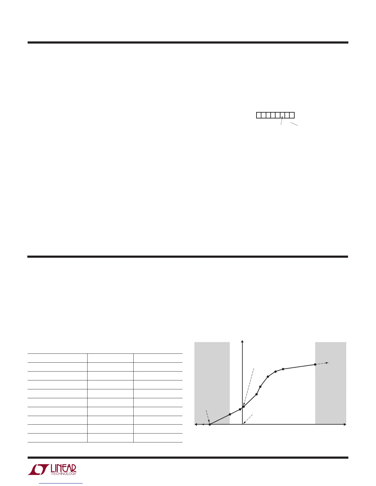
Figure 38. Custom Thermocouple Example (mV vs Kelvin)
2983 F38
TEMPERATURE (K)
p9
p8
p7
p6
p5
p4
p3
(0mV, 0K)
NOTE:
P0 SHOULD BE THE
EXTRAPOLATION
POINT TO 0K
VOLTAGE (mV)
p2
p1
p0
VOLTAGE < p1
SOFT FAULT
CONDITION
VOLTAGE > p9
SOFT FAULT
CONDITION
(0mV, 273.15K)
CUSTOM THERMOCOUPLES
Custom Thermocouple Example
In this example, a simplified thermocouple curve is
implemented (see Figure 38). Points P1 to P9 represent
the normal operating range of the custom thermocouple.
Voltage readings above point P9 result in a soft fault and
the reported temperature is a linear extrapolation using