LTC2983
28
2983fc
For more information www.linear.com/LTC2983
APPLICATIONS INFORMATION
RTD MEASUREMENTS
(2) Sense Resistor Channel Pointer
RTD measurements are performed ratiometrically relative
to a known R
SENSE
resistor. The sense resistor channel
pointer field indicates the differential channel the sense
resistor is tied to for the RTD (see Table 27). Sense resis-
tors are always measured differentially.
Table 26. RTD Type
(1) RTD TYPE
B31 B30 B29 B28 B27 RTD TYPE
0 1 0 1 0 RTD PT-10
0 1 0 1 1 RTD PT-50
0 1 1 0 0 RTD PT-100
0 1 1 0 1 RTD PT-200
0 1 1 1 0 RTD PT-500
0 1 1 1 1 RTD PT-1000
1 0 0 0 0 RTD 1000 (α=0.00375)
1 0 0 0 1 RTD NI-120
1 0 0 1 0 RTD Custom
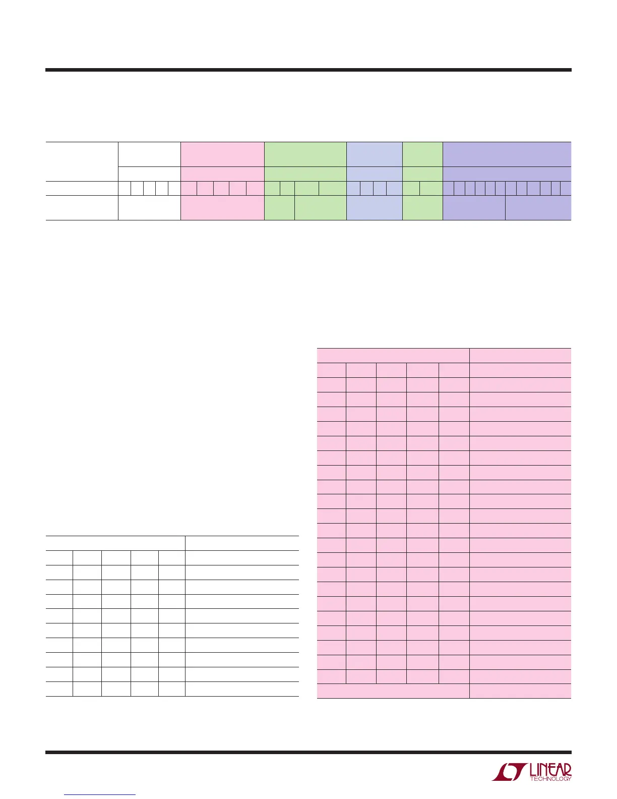
Table 25. RTD Channel Assignment Word
(1) RTD TYPE (2) SENSE RESISTOR
CHANNEL POINTER
(3) SENSOR
CONFIGURATION
(4) EXCITATION
CURRENT
(5) RTD
CURVE
(6) CUSTOM RTD DATA POINTER
TABLE 26 TABLE 27 TABLE 28 TABLE 29 TABLE 30 TABLES 72 TO 74
Measurement Class 31 30 29 28 27 26 25 24 23 22 21 20 19 18 17 16 15 14 13 12 11 10 9 8 7 6 5 4 3 2 1 0
RTD Type = 10 to 18 R
SENSE
Channel
Assignment [4:0]
2, 3, 4
Wire
Excitation
Mode
Excitation
Current [3:0]
Curve
[1:0]
Custom Address
[5:0]
Custom Length – 1
[5:0]
Table 27. Sense Resistor Channel Pointer
(2) SENSE RESISTOR CHANNEL POINTER
B26 B25 B24 B23 B22 SENSE RESISTOR CHANNEL
0 0 0 0 0 Invalid
0 0 0 0 1 Invalid
0 0 0 1 0 CH2-CH1
0 0 0 1 1 CH3-CH2
0 0 1 0 0 CH4-CH3
0 0 1 0 1 CH5-CH4
0 0 1 1 0 CH6-CH5
0 0 1 1 1 CH7-CH6
0 1 0 0 0 CH8-CH7
0 1 0 0 1 CH9-CH8
0 1 0 1 0 CH10-CH9
0 1 0 1 1 CH11-CH10
0 1 1 0 0 CH12-CH11
0 1 1 0 1 CH13-CH12
0 1 1 1 0 C
H14-CH13
0 1 1 1 1 CH15 -CH14
1 0 0 0 0 CH16-CH15
1 0 0 0 1 CH17-CH16
1 0 0 1 0 CH18-CH17
1 0 0 1 1 CH19-CH18
1 0 1 0 0 CH20-CH19
All Other Combinations Invalid
Channel Assignment – RTD
For each RTD tied to the LTC2983, a 32-bit channel as-
signment word is programmed into a memory location
corresponding to the channel the sensor is tied to (see Table
25). This word includes (1) RTD type, (2) sense resistor
channel pointer, (3) sensor configuration, (4) excitation
current, (5) RTD curve, and (6) custom RTD data pointer.
(1) RTD Type
The RTD type is determined by the first five input bits B31
to B27 as shown in Table 26. Linearization coefficients
for RTD types PT-10, PT-50, PT-100, PT-200, PT-500,
PT-1000, and NI-120 with selectable common curves
(α = 0.003850, α = 0.003911, α = 0.003916, and
α = 0.003926) are built into the device. If custom RTDs
are used, RTD Custom can be selected. In this case, user
specific data can be stored in the on-chip RAM starting
at the address defined by the custom RTD data pointers.