LTC2983
54
2983fc
For more information www.linear.com/LTC2983
APPLICATIONS INFORMATION
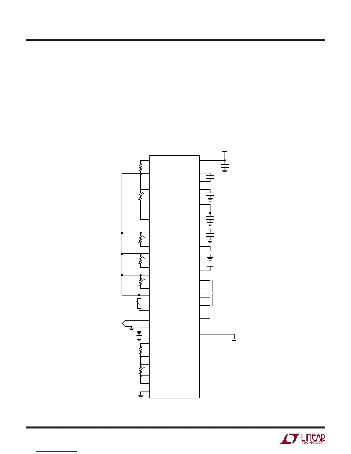
Typical Application RTD and Thermistor Measurements
The LTC2983 includes 20 fully configurable analog input
channels. Each input channel can be configured to accept
any sensor type. Figure 32 shows a typical application
digitizing multiple RTDs and thermistors. Each RTD/
thermistor requires a sense resistor which can be shared
with multiple sensors. RTDs can be configured as 2, 3,
or 4-wire topologies. For example, a single sense resistor
(CH1, CH2) is shared between a 4-wire RTD (CH4, CH3), a
2-wire RTD (CH7, CH6), two 3-wire RTDs (CH9, CH8 and
CH11, CH10) and a thermistor (CH13, CH12). This can
be mixed with diode sensors (CH15) and thermocouples
(CH14). Sense resistors (CH17, CH16) can also be dedi-
cated to specific sensors, in this case a 4-wire RTD (CH19,
CH18). Current is applied through both the sense resistor
and RTD/Thermistor, the resulting voltages are simulta-
neously measured and the results are output in °C or °F.
Figure 32. Typical RTD/Thermistor Application
CH2
CH3
CH4
CH5
CH6
CH7
CH8
CH9
CH11
CH12
CH13
CH14
CH15
CH10
CH1
Q1
Q2
Q3
V
DD
R
SENSE
R
SENSE
CS
SDI
SDO
SCK
V
REFOUT
V
REFP
16
48
47
46
13
14
11
43
42
41
40
39
38
37
2, 4, 6, 8, 45
2.85V TO 5.25V
17
4-WIRE
RTD
2-WIRE
RTD
3-WIRE
RTD
3-WIRE
RTD
4-WIRE
RTD
18
19
20
21
22
23
24
25
26
27
28
29
30
31
32
33
34
35
36
2983 F32
CH16
CH17
CH18
CH19
CH20
COM
0.1µF
10µF
10µF
1µF
V
REF_BYP
1µF
LDO
10µF
(OPTIONAL, DRIVE
LOW TO RESET)
SPI INTERFACE
1, 3, 5, 7, 9, 12, 15, 44
RESET
INTERRUPT
GND