LTC2983
44
2983fc
For more information www.linear.com/LTC2983
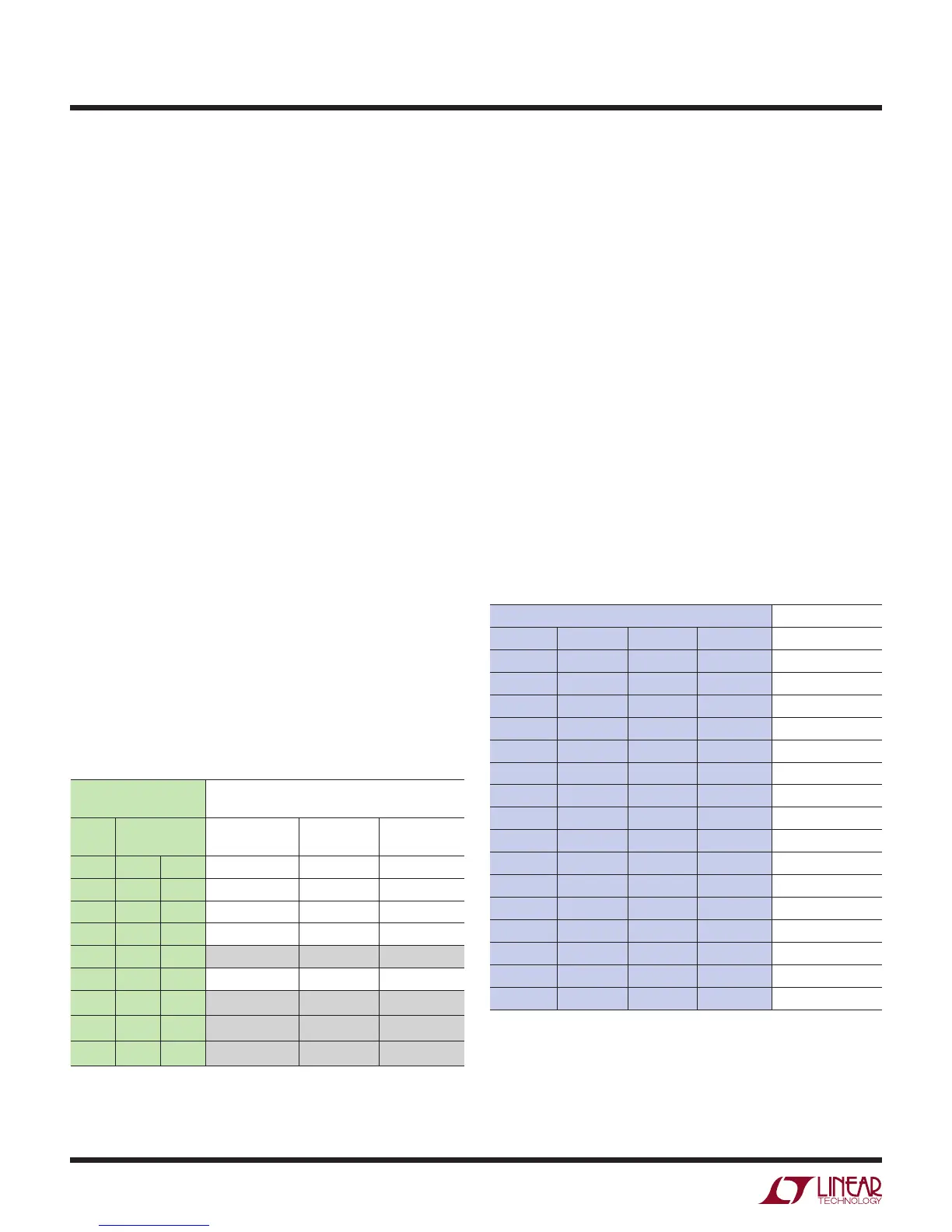
Table 52. Sensor Configuration Data
(3) SENSOR
CONFIGURATION
SGL EXCITATION
MODE
SINGLE-ENDED/
DIFFERENTIAL
SHARE
R
SENSE
ROTATE
B21 B20 B19
0 0 0 Differential No No
0 0 1 Differential Yes Yes
0 1 0 Differential Yes No
0 1 1 Reserved
1 0 0 Single-Ended No No
1 0 1 Reserved
1 1 0 Reserved
1 1 1 Reserved
APPLICATIONS INFORMATION
(2) Sense Resistor Channel Pointer
Thermistor measurements are performed ratiometrically
relative to a known R
SENSE
resistor. The sense resistor
channel pointer field indicates the differential channel
the sense resistor is tied to for the current thermistor
(see Table 27).
(3) Sensor Configuration
The sensor configuration field is used to define various
thermistor properties. Configuration bit B21 is set high
for single-ended (measurement relative to COM) and low
for differential (see Table 52).
The next sensor configuration bits (B19 and B20) deter-
mine the excitation current mode. These bits are used to
enable R
SENSE
sharing, where one sense resistor is used
for multiple thermistors. In this case, the thermistor ground
connection is internal and each thermistor points to the
same R
SENSE
channel.
Bits B19 and B20 are also used to enable excitation current
rotation to automatically remove parasitic thermocouple
effects. Parasitic thermocouple effects may arise from
the physical connection between the thermistor and the
measurement instrument. This mode is available for dif-
ferential thermistor configurations using internal current
source excitation.
(4) Excitation Current
The next field in the channel assignment word (B18 to B15)
controls the magnitude of the excitation current applied to
the thermistor (see Table 53). In order to prevent hard or
soft faults, select a current such that the maximum volt-
age drop across the sensor or sense resistor is nominally
1.0V. The LTC2983 has no special requirements related
to the ratio between the voltage drop across the sense
resistor and the sensor. Consequently, it is possible to
have a sense resistor several orders of magnitude smaller
than the maximum sensor value. For optimal performance
over the full thermistor temperature range, auto ranged
current can be selected. In this case, the LTC2983 conver-
sion is performed in three cycles (instead of the standard
two cycles) (see Table 64). The first cycle determines the
optimal excitation current for the sensor resistance value
and R
SENSE
value. The following two cycles use that cur-
rent to measure the thermistor temperature.
Table 53. Excitation Current for Thermistors
(4) EXCITATION CURRENT
B18 B17 B16 B15 CURRENT
0 0 0 0 Reserved
0 0 0 1 250nA
0 0 1 0 500nA
0 0 1 1 1µA
0 1 0 0 5μA
0 1 0 1 10μA
0 1 1 0 25μA
0 1 1 1 50μA
1 0 0 0 100µA
1 0 0 1 250µA
1 0 1 0 500µA
1 0 1 1 1mA
1 1 0 0 Auto Range*
1 1 0 1 Invalid
1 1 1 0 Invalid
1 1 1 1 Reserved
*Auto Range not allowed for custom sensors
(5) Steinhart-Hart Address/Custom Table Address
See Custom Thermistors section near the end of this data
sheet for more information.