LTC2983
46
2983fc
For more information www.linear.com/LTC2983
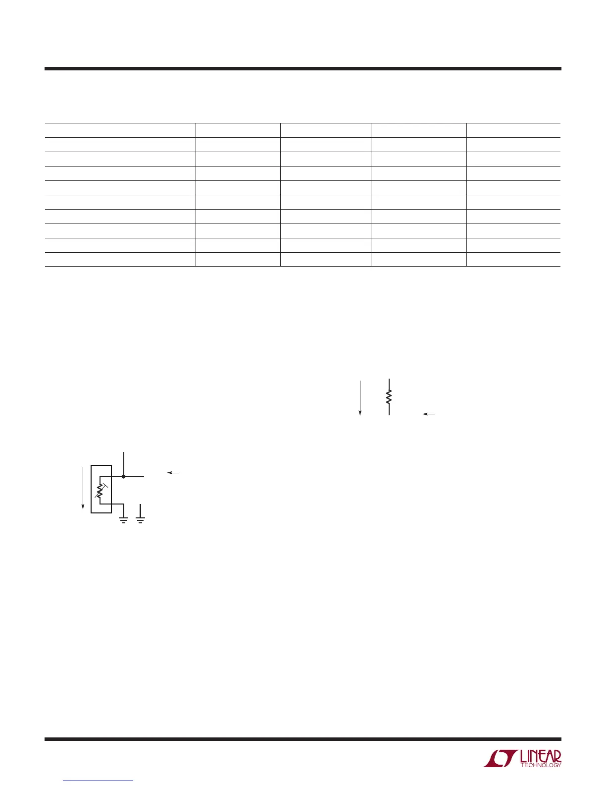
Example: Single-Ended Thermistor
The simplest thermistor configuration is the single-ended
configuration. Thermistors using this configuration share
a common ground (COM) between all sensors and are
each tied to a unique sense resistor (R
SENSE
sharing is
not allowed for single-ended thermistors). Single-ended
thermistors follow the convention shown in Figure 22.
Terminal 1 ties to ground (COM) and terminal 2 ties to
CH
THERM
and the sense resistor. Channel assignment
data (see Table 50) is mapped to memory locations cor-
responding to CH
THERM
.
APPLICATIONS INFORMATION
Sense resistor channel assignments follow the general
convention shown in Figure 23. The sense resistor is tied
between CH
RSENSE
and CH
RSENSE-1
, where CH
RSENSE
is tied
to the 2nd terminal of the thermistor. Channel assignment
data (see Table 33) is mapped into the memory location
corresponding to CH
RSENSE
.
Table 55. Thermistor Temperature/Resistance Range
THERMISTOR TYPE MIN (Ω) MAX (Ω) LOW Temp Limit (°C) HIGH Temp Limit (°C)
Thermistor 44004/44033 2.252kΩ at 25°C 41.9 75.79k –40 150
Thermistor 44005/44030 3kΩ at 25°C 55.6 101.0k –40 150
Thermistor 44007/44034 5kΩ at 25°C 92.7 168.3k –40 150
Thermistor 44006/44031 10kΩ at 25°C 237.0 239.8k –40 150
Thermistor 44008/44032 30kΩ at 25°C 550.2 884.6k –40 150
Thermistor YSI 400 2.252kΩ at 25°C 6.4 1.66M –80 250
Spectrum 1003K 1kΩ at 25°C 51.1 39.51k –50 125
Thermistor Custom Steinhart-Hart N/A N/A N/A N/A
Thermistor Custom Table Second Table Entry Last Table Entry
Figure 22. Single-Ended Thermistor Channel Assignment
Convention
Figure 23. Sense Resistor Channel Assignment Convention
2983 F22
2
1
CH
THERM
COM
EXCITATION
CURRENT
FLOW
= CH
THERM
(1 ≤ THERM ≤ 20)
2ND TERMINAL TIES TO SENSE RESISTOR (CH
RSENSE
)
CHANNEL
ASSIGNMENT
CH
RSENSE-1
CH
RSENSE
R
SENSE
EXCITATION
CURRENT
FLOW
= CH
RSENSE
(2≤ RSENSE ≤ 20)
CHANNEL
ASSIGNMENT