Images are for illustration only and may differ from components supplied
Link Research Ltd www.linkres.co.uk Support UK/Europe + (44) 1923 474099 USA +(1)9786715700
Page 16 of 31 CL140045 Issue C Link L1500 Series System Manual
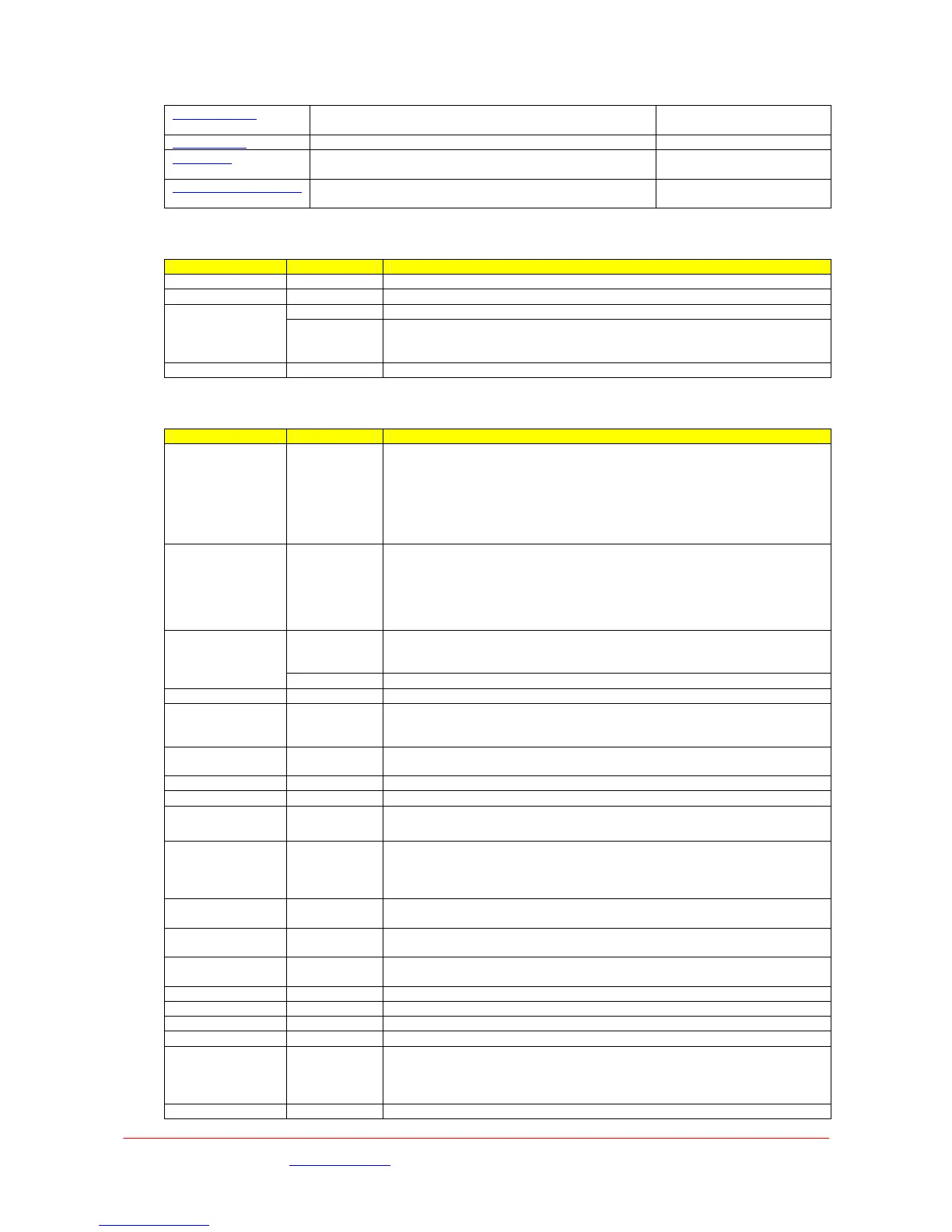
Decoder Menu Shows Service name and Decoder status, selects
required audio configuration,
RS232 Menu Configure RS232 port
Unit Menu Configure Down Converter, Shows code versions,
selects operating mode
CCU Camera Control If L1255 is connected, selects UHF frequency and OCP
type
Memory Menu
Sub menu Options Comments
Store –Config? Config 1…9 Stores the current settings into selected memory location 1 to 9
Load – Config? Config 1…9 Loads stored settings from the selected memory location 1 to 9
No Does not change the current active settings.
Default Restore
No
Yes Restores the current active settings to factory defaults.
NB – If the receiver cannot be set up, it is worth using this option and
then restarting the set-up again.
Last Config # None Shows the last configuration (memory) that was used.
Demodulator Menu
Sub menu Options Comments
IPFreq
#.###GHz
Enter
required
frequency
The transmit frequency of the camera transmitter is entered here. Note
that although tuning steps of 10kHz can be entered on the screen, when
the enter key is pressed the receiver locks to the nearest 1MHz step.
If the down converter settings in the Unit menu are set to L3010 or
L3020 (Link), the frequency is automatically copied to the OFDM Demod
2 menu. If the down converter setting is set to Other, a frequency can
be entered that does not have to be the same as in OFDM Demod 2.
DConvLO
#.###GHz
Enter
required
frequency, if
required.
The Downconverter local oscillator frequency is entered here. Where
Link down converters are being used, the figure is automatically entered
from a menu setting in the Unit menu. For down converters from other
manufacturers, set the Downconverter type in the unit menu to OTHER
and enter the local oscillator frequency here.
High Selects the local oscillator output mix for the Downconverter.
Automatically entered for Link downconverters entered in the unit menu.
But can be set. for other downconverters.
LoSide Low
Low As above. Means that the downconverted frequency is higher
Polarity ??? None MUST be matched to transmitter.
Width #MHz
20/10/8/7/6
MHz
Indicator
Channel width indicator as set by the transmitter. 20Mhz and 10Mhz
only is LMS-T mode
Guard ??? 1/8,1/16,1/3
2
MUST be match to the transmitter Default 1/16
Lock Indicator Yes/No Indicates whether the Demodulator has locked onto the incoming signal
Modulation ??? None Automatically detected from the incoming signal.
FEC Rate ??? None Automatically detected from the incoming signal.
SNRA
#.###dBm
None
A measure of signal quality measurement. The reading shown is an
instantaneous measurement taken at the time the return key is pressed.
To update the reading, the menu must be exited and then re-entered.
Note value is not calibrated
SNRB
#.###dBm
Display for RF2
SNRC
#.###dBm
Display for RF3
SNRD
#.###dBm
Display for RF4
InA Level ??? dB None Displays input level into RF1
InB Level ???dB None Displays input level into RF2
InCevel ??? dB None Displays input level into RF3
InDLevel ???dB None Displays input level into RF4
PreBER
#####.####e
None
Pre viterbi error rate automatically detected from the incoming signal.
The reading shown is an instantaneous measurement taken at the time
the return key is pressed. To update the reading, the menu must be
exited and then re-entered.
PostBER Post viterbi error rate automatically detected from the incoming signal.
 Loading...