Rev: 11.19.20 Page 19 CCD-0002764
Setting the ACS Stop Procedure
Setting the UP Position
1. Make sure the safety belts are unfastened.
2. Turn the key switch to the ON position (Fig. 37D) located on the key pad.
3. Press and hold the UP arrow-shaped button (Fig. 37A) on the key pad. A green LED light (Fig. 37C) on
the key pad will turn on in the direction the bed is moving. The bed will keep moving until the pre-set
stop position is reached.
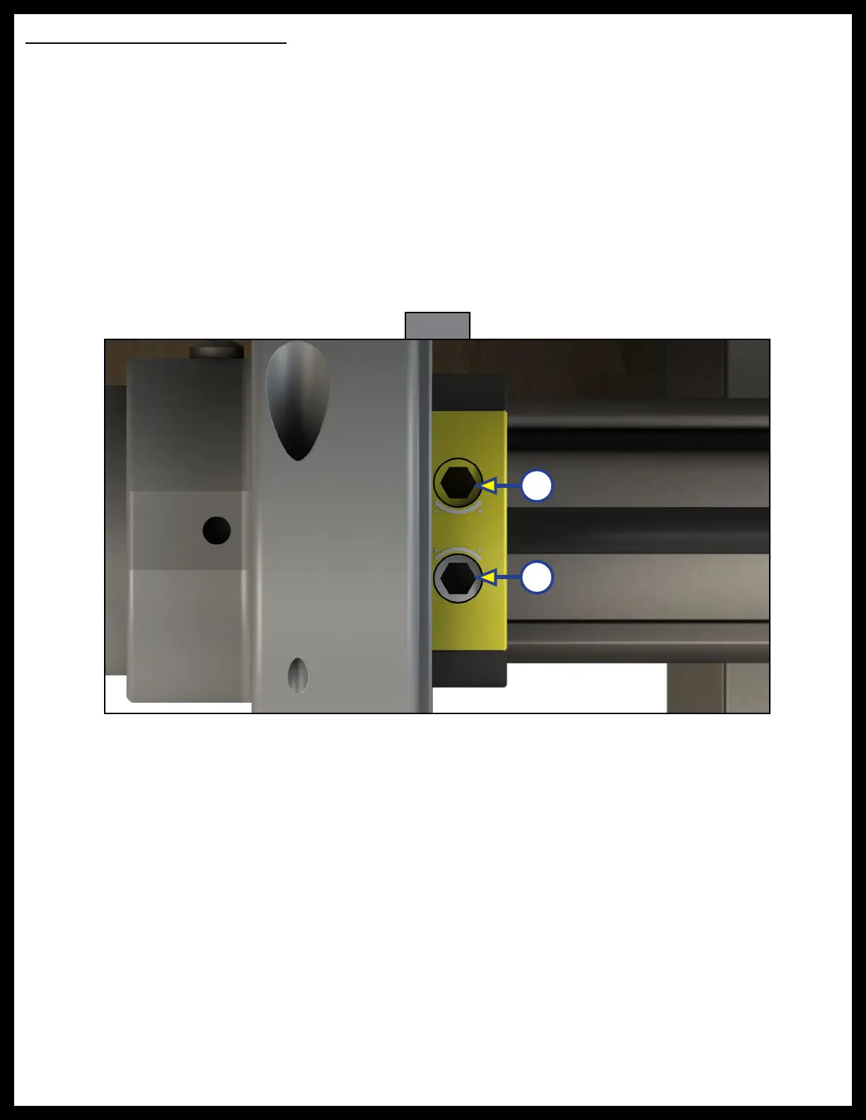
4. If the bed lift stops too low, turn the white screw (Fig. 31B) in the ACS module counterclockwise. This will
allow the bed lift to move higher. If the bed lift stops too high, turn the white screw (Fig. 31B) clockwise
until the bed lift stops lower.
5. One full rotation of the screw is approximately 25.4 mm (1.0 in) of movement up or down.
6. Press the UP arrow (Fig. 37A) and DOWN arrow (Fig. 37B) to run the bed lift system after each
adjustment of the screw. If necessary, repeat this procedure until desired stop location is obtained.
Setting the DOWN Position
1. Make sure the safety belts are unfastened.
2. Turn the key switch to the ON position (Fig. 37D) located on the key pad.
3. Press and hold the DOWN arrow-shaped button (Fig. 37B) on the key pad. A green LED light (Fig. 37C)
on the key pad will turn on in the direction the bed is moving. The bed will keep moving until the
pre-set stop position is reached.
4. If the bed lift stops too high, turn the yellow screw (Fig. 31A) counterclockwise. This will allow the bed
lift to move lower. If the bed lift stops too low, turn the yellow screw (Fig. 31A) clockwise until the bed
lift stops higher.
5. One full rotation of the screw is approximately 25.4 mm (1.0 in) of movement up or down.
6. Press the UP arrow (Fig. 37A) and DOWN arrow (Fig. 37B) to run the bed lift system after each
adjustment of the screw. If necessary, repeat this procedure until desired stop location is obtained.
Fig. 31
A
B