Rev: 11.19.20 Page 4 CCD-0002764
Resources Required
Installation
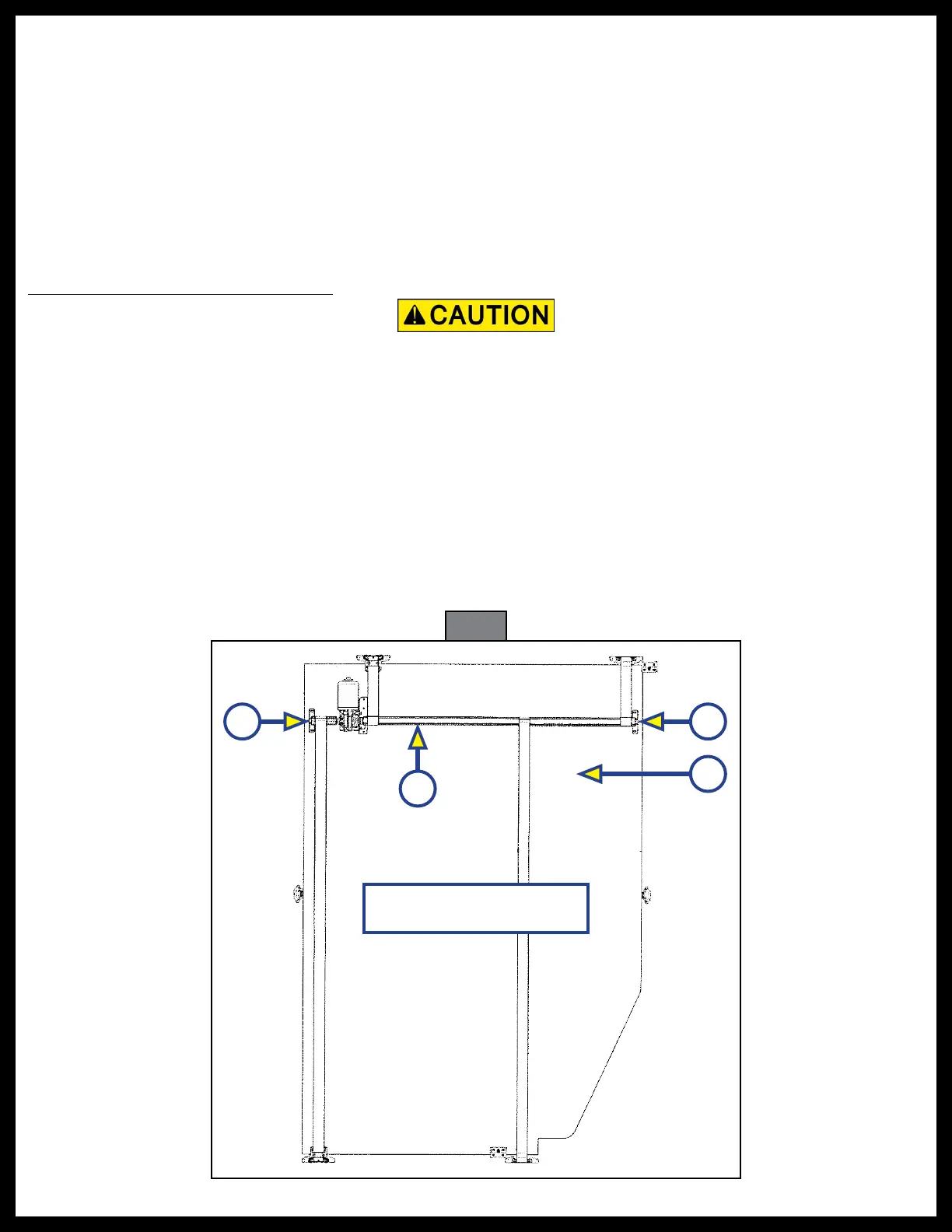
NOTE: The assembled bed frame should stay bottom facing up throughout the component installation.
Drive Shaft and Motor Installation
Always wear eye protection when performing service, maintenance or installation procedures.
Other safety equipment to consider would be hearing protection, gloves and possibly a full face
shield, depending on the nature of the task.
NOTE: For the drive shaft to fit the dimensions of the bed lift and to install the motor, the drive shaft must
be cut and material removed for the motor to be installed on the drive shaft.
1. Place the drive shaft (Fig. 1A) on the bed frame (Fig. 1B) with the drive shaft centering brackets (Fig. 1C)
on the side rails of the bed. If the drive shaft (Fig. 1A) is too long, and the drive shaft centering brackets
(Fig. 1C) are off the bed frame, center one side of the drive shaft centering bracket on the bed rail and
measure the excess distance on the opposite side of the drive shaft to make the drive shaft centering
bracket centered with the opposite side bed frame rail. Add the measurement of the excess drive shaft
to the measurement when cutting the shaft to install the motor.
Fig. 1
A
C C
B
Bottom of Bed Facing Up
• Cordless or electric drill or
screw gun
• Appropriate drive bits
• Appropriate drill bits
• Appropriate cutting tool for
metal
• Appropriate fasteners
• Socket wrench (8 mm)
• Wiring per governing codes
• Super Lube® Grease
• Measuring tape
• Pencil
• (2) Relay's