Rev: 11.19.20 Page 5 CCD-0002764
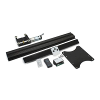
2. Cut and remove 120 mm (4.7 in) (Fig. 2, orange lines) from the drive shaft (Fig. 2A) including the excess
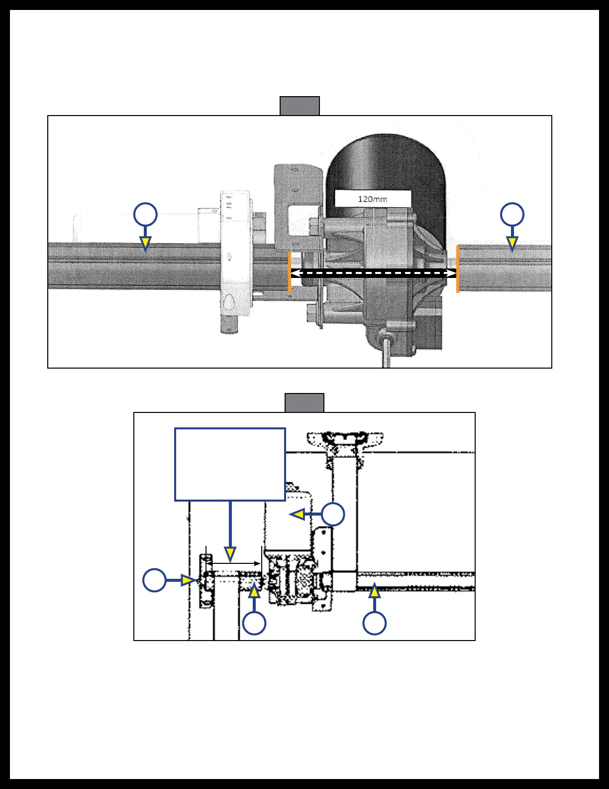
drive shaft, measurement from step 1, for the drive shaft centering brackets (Fig. 3A) and the motor
(Fig. 3B) to be installed on the drive shaft. The motor (Fig. 3B) has to be between the two drive shafts
(Fig. 3C) in the preferred position but keeping a minimum length for each shaft of at
least 185 mm (7.3 in).
Fig. 2
Fig. 3
A A
185 mm (7.3 in)
Minimum Distance
on One Side
of the Drive Shaft
A
B
C C