Rev: 11.19.20 Page 9 CCD-0002764
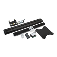
18. Measure from the outside end rail to the end of the drive shaft header center brackets. There should be a
57.2 mm (2 1/4 in) gap (Fig. 9) from the end of the rail to the edge of the drive shaft header center bracket.
Move the long and short drive shaft header center brackets into place so that both sides are even.
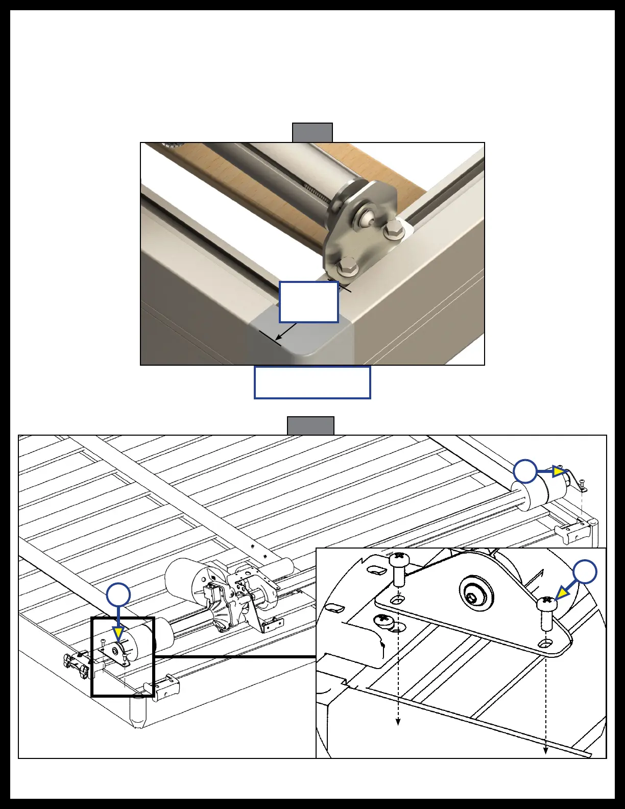
19. Attach the long drive shaft header assembly centering bracket (Fig. 10C) to the side rail with two
M5 - 0.8 x 10 mm screws (Fig. 10B).
20. Attach the short drive shaft header assembly center bracket (Fig. 10A) to the side rail with two
M5 - 0.8 x 10 mm screws (Fig. 10B).
57.2 mm
(2.25 in)
Fig. 9
For Reference Only
Fig. 10
A
C
B