Rev: 09.11.20 Page 6 CCD-0001360-AU
Fig. 6
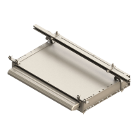
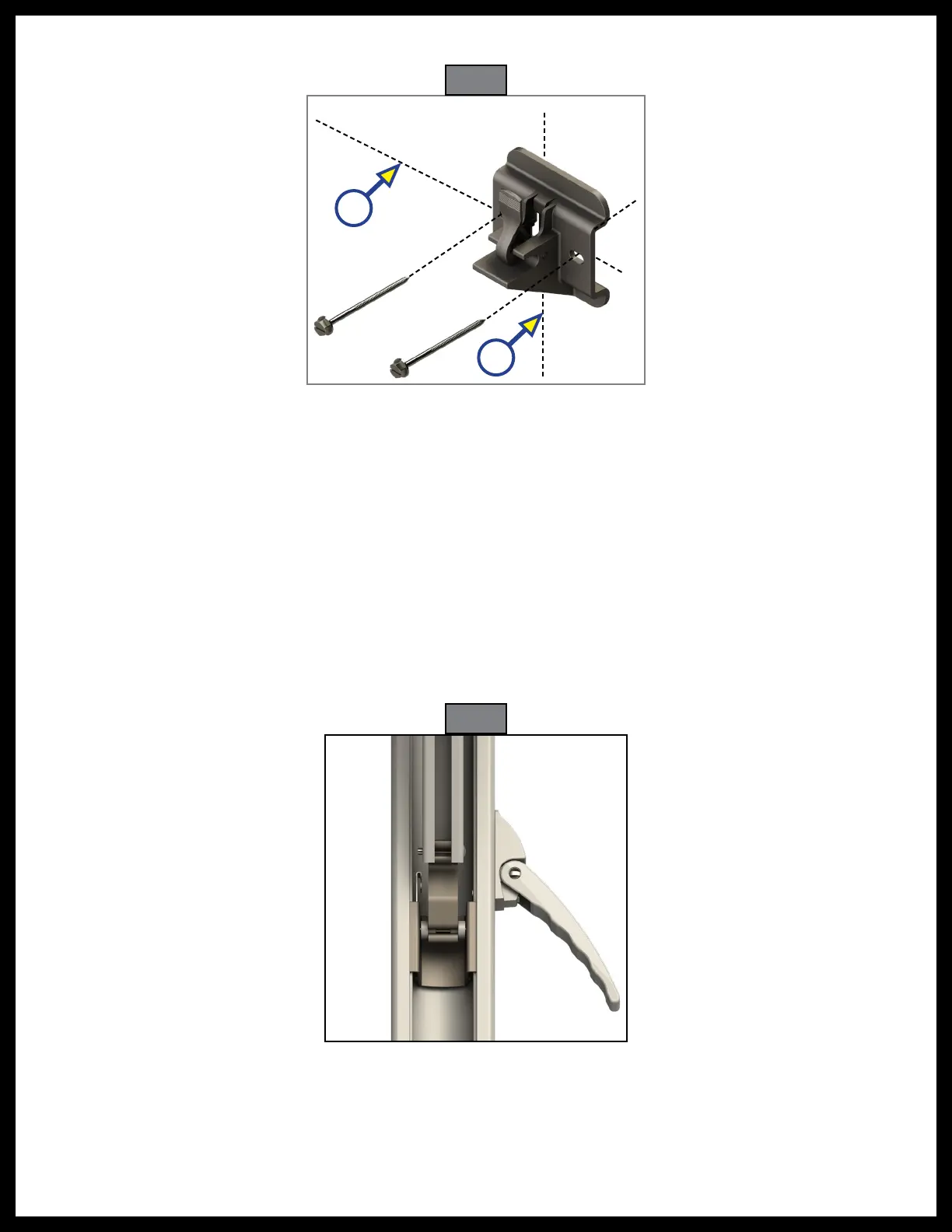
D. Attach the bracket using the
¼
" x 3" lag screws or equivalent (not provided) (Fig. 5).
Fig. 5
A
B
Note: All screws supporting the awning assembly MUST have a backer within the structure of the wall of
the unit. Refer to the unit manufacturer for proper location.
4. Repeat step 3 for the other end of the awning.
Mounting the Awning
1. Measure the distance from the awning rail channel to the lower mounting bracket fastening point.
2. Compare the distance from the center of the roll tube and the support arm assembly foot to the
measurement in Step 1 and adjust the support arm assembly to make both distances equal.
A. Open the support arm assembly handle (Fig. 6) and slide the outer arm lower channel (Fig. 7,
channel #2) up or down to desired height.
B. Close the handle and slide the outer arm lower channel (Fig. 7, channel #2) until the locking pin clicks
into the nearest positioning hole.

 Loading...