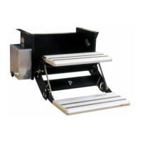
The Lippert SlimRack® Plus Slide-Out system is designed to maximize interior RV space by providing added comfort and a practical solution for additional space needs. This system combines versatile above-floor placement with an attractive, seamless flush-floor style, offering a sleek, polished, high-end look without a step up.
Function Description:
The SlimRack Plus Slide-Out system operates to extend and retract a slide-out room in an RV. It features a controller that manages the movement of two motors, ensuring synchronization between the two sides of the slide-out. The system is designed to self-synchronize, detect end-of-travel, and identify and store faults. It also incorporates electronic protections to safeguard the slide-out when certain faults are detected.
Operating Modes:
The controller offers multiple operating modes:
- Normal Operating Mode: This is the standard mode for extending and retracting the slide-out while maintaining synchronization between the two sides. In this mode, the controller performs self-synchronization, end-of-travel detection, fault detection, and electronic protection.
- Electronic Override Mode: This mode disables fault detection and electronic protections. The slide-out motors are driven without these safeguards, meaning the slide-outs will not self-synchronize or detect end-of-travel. Caution is advised when using this mode, as driving the slide-out flanges into the RV wall or skewing the slide-out box can cause damage. To enter this mode, the on-controller mode button is pressed seven times and held on the last press. The LEDs will rapidly blink one after another while active. The controller can return to normal operating mode by pressing and holding the mode button for at least one second or automatically after two minutes. In this mode, either side can be driven independently by unplugging the opposite side's motor connector, or both sides can be moved simultaneously if both connectors are connected.
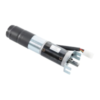
- Manual Override Mode: In the event of power loss to the slide-out motor(s), the slide-out room can be manually retracted. This involves gaining access to the vertical channel assembly, removing the motor cover, loosening the motor retaining screw, and removing the motor. The slide-out room is then pushed uniformly into the retracted position. After retraction, the motors must be re-installed and the motor retaining screw tightened. A transit bar (slide-out locking bar) can also be used to secure the room. Servicing by an OEM-authorized dealer is recommended as soon as possible, and the slide-out should not be operated until service is complete to prevent damage.
- Alternate Override Modes: If other override methods fail, the slide-out can be manually retracted using a ratchet and socket attached to the end of the coupler. This involves removing the motor, seating a ratcheting wrench with a 3" extension and 5/8" deep well socket (or a 15 mm 12-point socket as an alternative) onto the coupler, and turning the wrench to bring the slide-out room in. Two people (one per side) with a ratchet and socket are recommended for uniform retraction. The slide-out room moves approximately 1/4" for every 30-40 degree turn of the wrench. Once retracted, the motors must be re-installed, the motor retaining screw tightened to 40 in-lbs, and a transit bar used.
Another alternate method involves turning the 1/2” square drive shaft of each vertical channel assembly using a 1/2" 8-point star socket (or a 15 mm 12-point socket).
Important Technical Specifications:
- Power Requirements: For operation, the engine or generator must be running, or the unit must be plugged into shore power to ensure ample voltage. For towable units, batteries must be fully charged.
- Motor Connections: The controller has connections for power input and extend/retract outputs to each motor. It also includes connections for an external switch, a parking brake input, and CAN communications to OneControl systems.
- Circuit Protection: The system incorporates a 30 Amp Circuit Breaker for protection.
- Motor Retaining Screw Torque: When re-installing motors, the motor retaining screw should be torqued to 40 in-lbs.
Usage Features:
- Simple Operation: The slide-out room is extended or retracted by pressing and holding a switch. A slight delay before movement is normal.
- Mode Button Functions: The mode button on the controller is used to perform a factory reset and switch between operating modes. Pressing the button a specific number of times and holding on the last press activates different functions. For example, pressing six times and holding enters electronic override mode, while pressing four times and holding performs a factory reset.
- Factory Reset and Initial Synchronization: A factory reset clears current synchronization and is necessary after swapping motors, reversing motor polarity, repairing motor harnesses, swapping controllers, or during initial installation. After a factory reset, an initial synchronization procedure must be performed, which involves fully retracting and extending the slide-out multiple times to ensure proper alignment and synchronization.
- LED Indications: The controller features LEDs that indicate operation status and faults.
- Synchronous blinking of green and red LEDs indicates motors are driving.
- Sequential blinking indicates faults. The green LED blinks once or twice to indicate the reporting mode, followed by one to several blinks of the red LED to indicate the specific fault.
- Both LEDs blink to acknowledge user selection when switching between modes.
- Five blinks indicate a factory reset.
- Rapid, alternating blinking indicates electronic override mode is active, with fault warnings and electronic protections disabled.
- QR Code: A QR code on the controller can be scanned with a mobile phone camera to access additional troubleshooting documentation.
Maintenance Features:
- Low Maintenance Design: The Lippert slide-out system is designed for very little maintenance.
- Gear Rack Inspection: When the slide-out room is extended, visually inspect the slide gear rack assemblies for excess dirt or foreign material and remove any debris.
- Lubrication: If the system squeaks or makes noises, apply a dry lubricant to prevent or stop the squeaking.