Rev: 09.19.23 Page 22 CCD-0007153
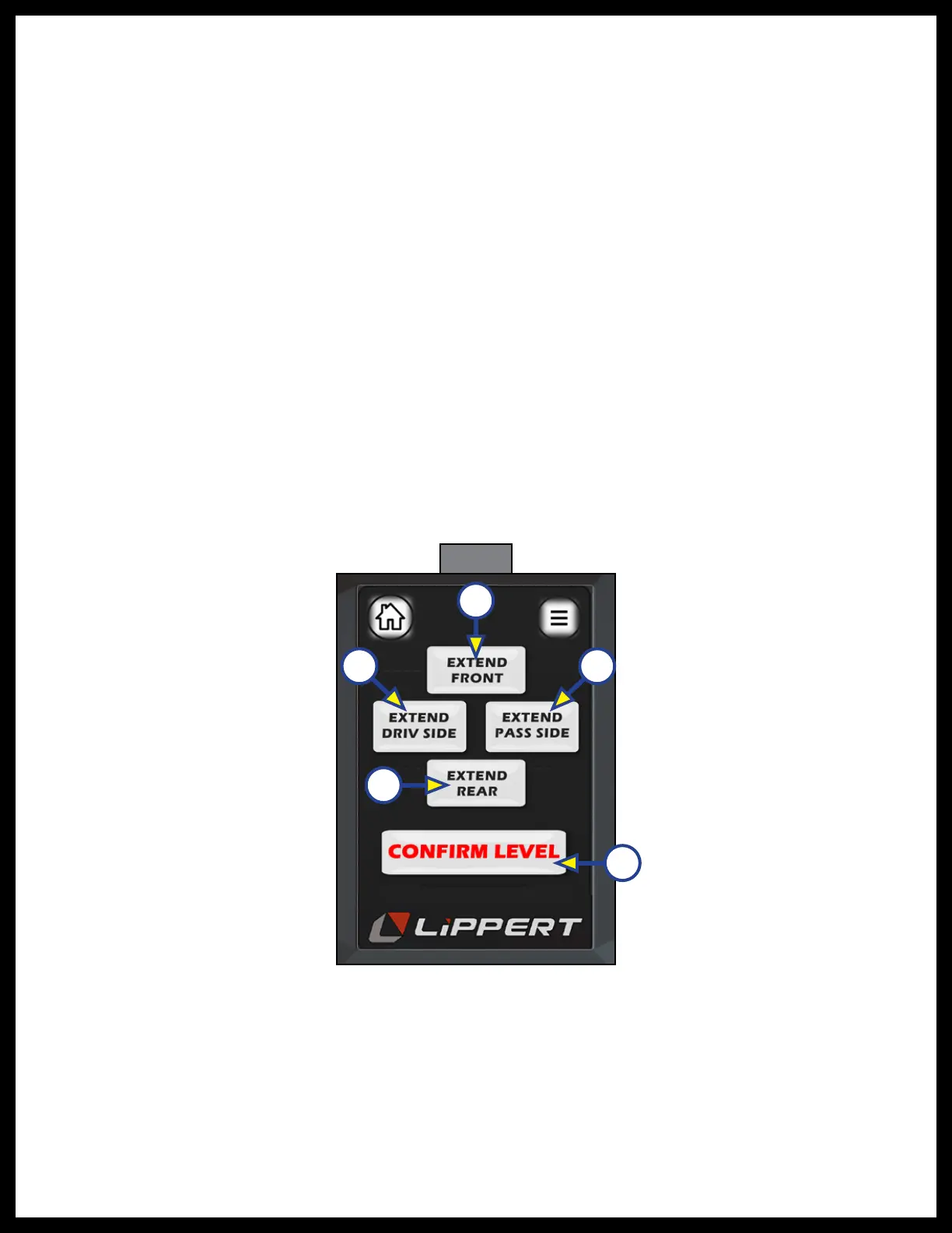
5. The next screen that follows (Fig. 48) shows four extend buttons that activates each pair of valves,
directional control valve and solenoid. The "CONFIRM LEVEL" button (Fig. 48E) is a latching button that
zeros out the control accelerometer and stores that exact position as level. After the initial calibration,
when the user presses “AUTO LEVEL”, the control recognizes that position as level and will bring the
coach to that position.
6. Level the coach in the manual "CALIBRATION" mode by using a carpenter’s level on the floor. Level
front to rear and then left to right.
A. Push the "EXTEND FRONT" (Fig. 48A) button until jacks contact the ground and lift the front of
the coach 1-2 inches. Continue to use the EXTEND REAR and EXTEND FRONT buttons until the
carpenter's level bubble is centered.
B. Push "EXTEND REAR" (Fig. 48D) button until jacks contact the ground and lift rear of coach.
Keep button depressed until the carpenter's level bubble is centered.
C. Push "EXTEND DRIV SIDE" (Fig. 48B) and "EXTEND PASS SIDE" (Fig. 48C) buttons until level
bubble is centered.
7. With the coach leveled, press “CONFIRM LEVEL” (Fig. 48E)
8. The touch pad is now in zero mode. If the coach has come out of it’s level condition, it can be reset
into level condition by following the procedure outlined in step 3.
NOTE: During the “auto level” process, if too much time has passed (180 seconds) or if control was calling
to extend pair of jacks but saw zero movement (angle change) meaning the cylinders have reached
full stroke, or coach is parked on too great of an incline (over 4.5 degrees) and cannot complete level
process. A "LEVELING ERROR" screen (Fig. 46) will appear. Press Home (Fig. 46A) or Menu (Fig. 46B)
icons to get out of this page.
Fig. 48
A
B
C
D
E