TP0003B
BM METER
Chap 2
Page 1
TECHNICAL DESCRIPTION
Chapter 2
TECHNICAL DESCRIPTION
CONTENTS
Para
General Information 1..............................................................................
Manifold 2.........................................................................................
Body Assembly 3..................................................................................
Dynamic Seals 4...................................................................................
Rotor Assembly 5..................................................................................
Calibrating Mechanism 6............................................................................
Mechanical Register 7..............................................................................
Meter Accessories 8................................................................................
Ticket Printer 9....................................................................................
Mechanical Preset Register and Valve 10.............................................................
Rate of Flow Indicator 11............................................................................
Temperature Compensator 12.......................................................................
Additive Mechanism 13.............................................................................
Strainer 14........................................................................................
Volume/Weight Adaptor 15..........................................................................
Air Separator 16...................................................................................
Flow Governor 17.................................................................................
Extended Counter Drive and Swivel 18................................................................
Trolley 19.........................................................................................
Masterload 20.....................................................................................
1 GENERAL INFORMATION
1.1 BM Series Bulkmeters are manufactured in three basic sizes with different ratings identified by a
series number. The series numbers, sizes, flow rates and a brief description of each series of meter
are shown in Table 1.
TABLE 1 - TYPES OF BULKMETER
MANIFOLD FLOW RANGE
ERIE
N
ins. mm imp. gals. litres
ENERAL DE
RIPTI
N
BM250 21/2 63 25 - 250 115 - 1140
BM950 3 76 30 - 300 130 - 1370
ingle capsule meters
BM450 3 76 45 - 450 200 - 2050
BM550 4 102 50 - 500 220 - 2280 Double capsule meters
BM350 4 102 55 - 550 250 - 2500
BM650 4 102 65 - 650 300 - 3000
BM750 6 152 65 - 650 300 - 3000
Triple capsule meters
BM850 6 152 85 - 850 387 - 3870 Special application only for low
viscosity/clean aviation fuel
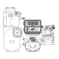
1.2 The BM series bulkmeters consist of three main assemblies, the manifold, body assembly and rotor
assembly, (Figure 2.1). The basic design of all the bulkmeters is similar. The higher rating of the
larger meters is achieved by bolting two or three body casings (capsules) together and fitting double
or triple rotor assemblies with a larger manifold to suit. A calibrating mechanism and Mechanical
Register are also attached to the front end cover. These can be replaced by a front cover
incorporating a pulse transmitter when required for electronic systems, such as Masterload.
 Loading...