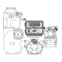
TP0003B
BM BULKMETER
Chap 5
Page 6
SERVICING
5.15 After removal,temporarily re-assemble each vane assembly to avoid mixing components.
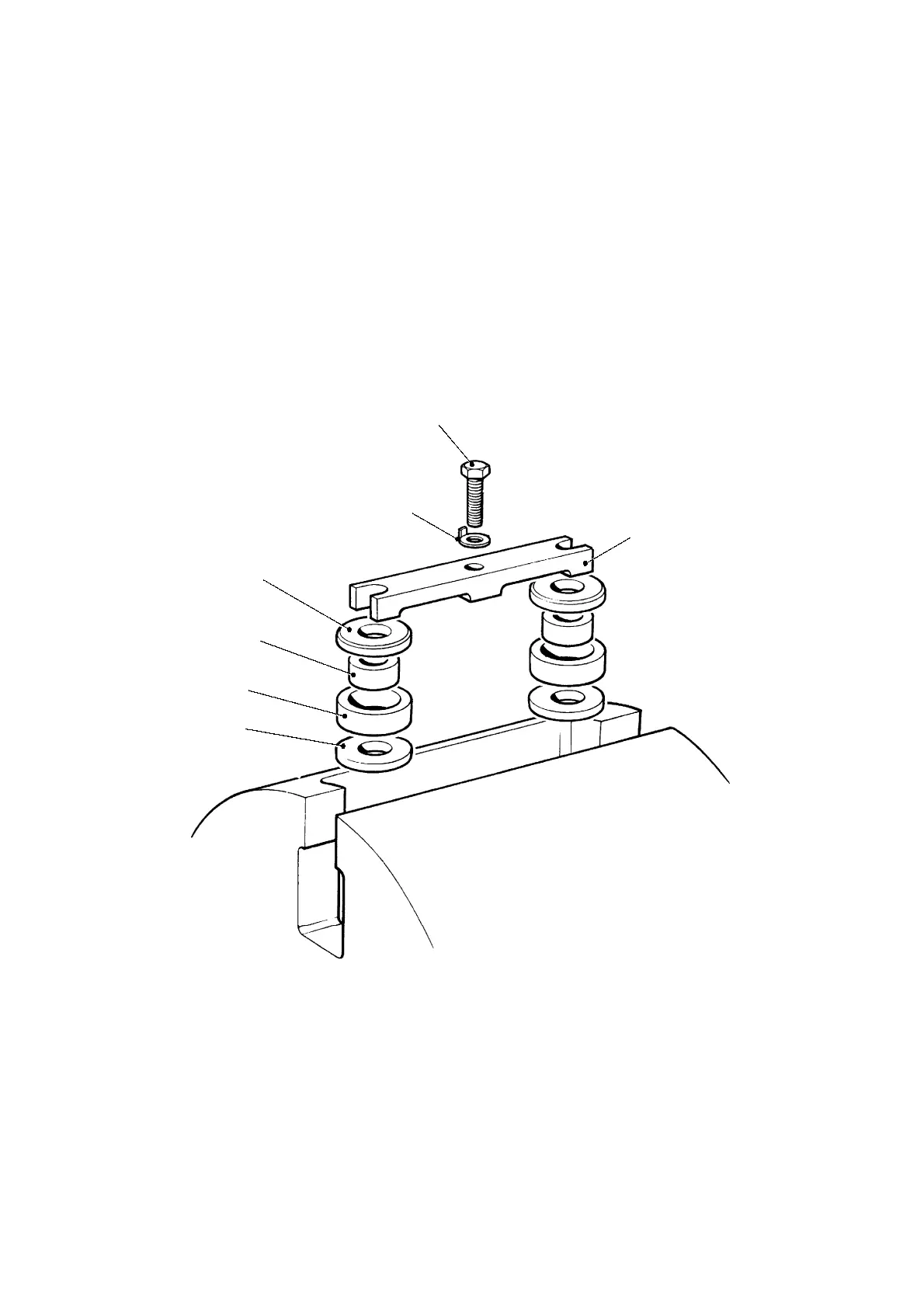
5.16 The four gland assemblies within the rotor may now be removed. Dismantle each assembly in turn to
ensure parts do not become mixed.
IMPORTANT: Gland Assemblies must be refitted in their original positions, it is recommended that
each is identified using a suitable marker.
5.17 To dismantle each assembly (refer to Fig.5.4), bend down the tab washer (33), remove the securing
screw (34) and clamp plate (32). Stretch a piece of cloth over the rotor recess to collect the parts
and turn the rotor upside down and allow the gland assemblies to fall.
FIG 5.4 GLAND ASSEMBLY
SECURING SCREW
TAB WASHER
GLAND WASHER
GLAND SEAL RING
GLAND WASHER
CLAMP PLATE
S13617
GLAND DISTANCE PIECE
 Loading...