TP0003B
BM BULKMETER
Chap 5
Page 10
SERVICING
10.2
10.3
10.4
10.5
10.6
10.7
10.8
If a new rotor is being fitted, the clearance between the inner covers and
rotor face must be checked.
If rotor is not being renewed continue with paragraph 10.6.
Fit rotor into body without compression spring (13).
Place a straight-edge across body of meter and using feeler gauges measure the clearance between
rotor face and underside of straight-edge. See Table 1 -- Fits and Clearances.
If the measured clearance is outside the figures stated then the meter and new rotor should be
returned to Liquid Controls for re-shimming, re-calibration and test.
Place the compression spring (13) in position in the inner rear cover boss, fit rotor (26), complete with
bearings (10) into the body (1).
Locate the inner front cover (5) into position over the dowels (4) and secure to the body with the two
screws (9) and a minimum of four equally spaced cover bolts (22).
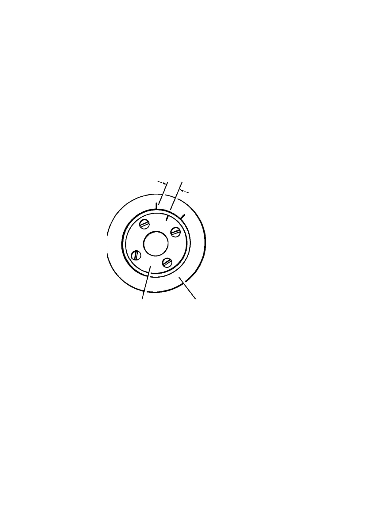
Mark a permanent line “X” (See Fig 5.7) approximately 6mm (0.25”) long from near the edge of the
adjuster.
LINE ‘X’ TO BE SET
EQUIDISTANT BETWEEN
LINES ‘Y’ AND ‘Z’
Y
Z
X
ADJUSTER BOSS
FIG 5.7 BEARING ADJUSTER CLEARANCE
10.9 Spin the rotor and screw the adjuster inwards until the rotor is heard to touch the inner REAR cover
(6). Mark the boss of the inner front cover in pencil with a line “Y” coinciding with line “X” on the
adjuster.
10.10 Spin the rotor and unscrew the adjuster until the rotor is heard to touch the inner FRONT cover.
Mark the boss, in pencil with a line “Z” coinciding with line “X” on the adjuster.
10.11 Identify the inner front cover, with adjuster fitted, with its particular rotor and body and remove the
cover . With a scriber make the lines “Y” and “Z” on the cover boss permanent. Check that the angle
between the two lines is between 45 deg and 57 deg for BM250 and BM900 meters, 62 deg and 76
deg for BM450 and BM550 meters and 76 deg and 95 deg for BM650 and BM750 meters.
10.12 Reset the bearing adjuster (11) by screwing the adjuster inwards to bring line “X” (Figure 5.7)
equidistant between lines “Z” and “Y”. Lock the adjuster with the counter sunk screw (12).
10.13 Withdraw the rotor from the body.
10.14 Assemble each gland as shown in Fig 5.4 (the chamfered edges of the lower gland washers (29) face
downwards). Ensure that each gland assembly is located in its correct rotor recess.
 Loading...