TP0003B
BM BULKMETER
Appendix to Chap 8
Page 1
Appendix to Chapter 8
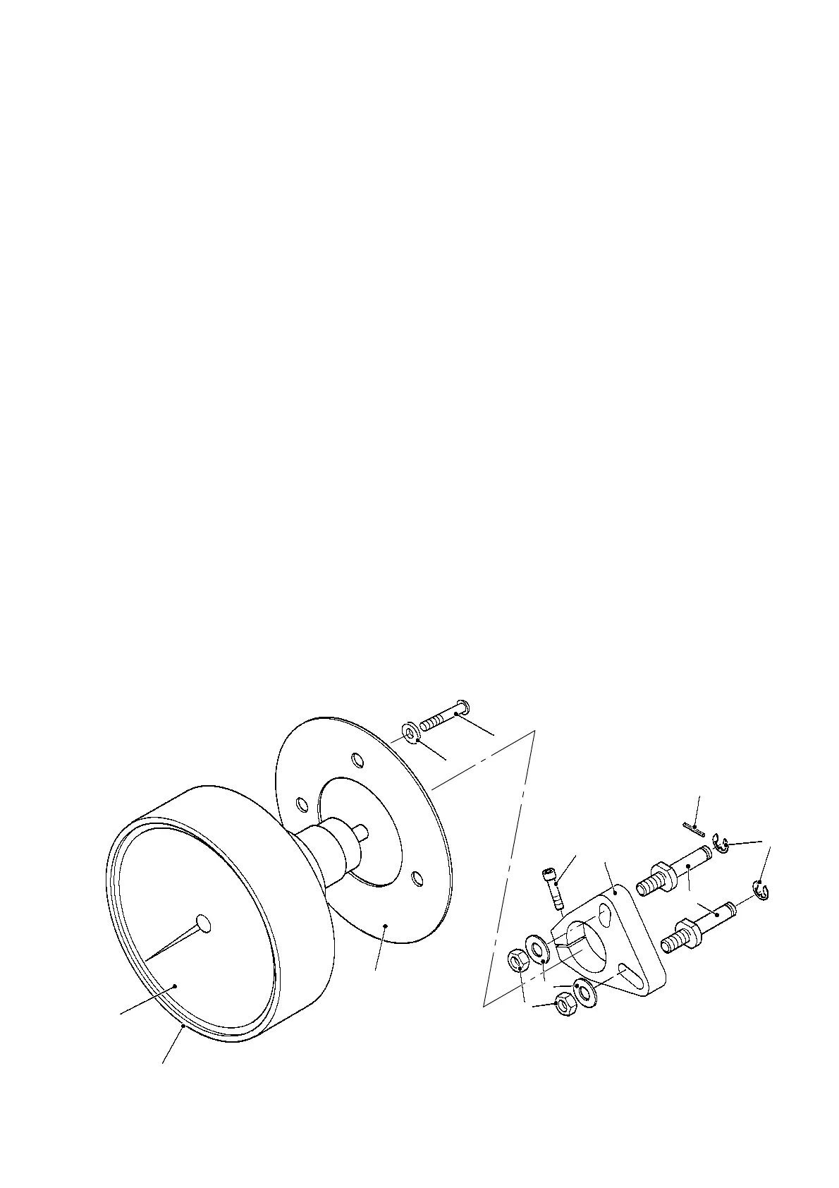
1 RATE OF FLOW INDICATORS FITTED TO OLDER (MK IIA) CALIBRATION
MECHANISM
1.1
To replace the rate of flow indicators on meters manufactured before 1997 it is nec
essary to replace
the rate of flow and cover assembly, since the rate of flow style changed at this time. Kits of parts to
do this are shown in Fig 8A.1. If in doubt quote the meter serial number to Liquid Controls spares
dept.
2 FITTING INSTRUCTIONS
2.1 Remove the Calmech cover (4 screws). Remove the ROF Indicator from the cover.
2.2 Units from LH discharge meters have 2 gears, those from RH discharge meters have 3. Transfer the
gears to the new assembly. Secure the gears using the circlips (9) and tension pin (6).
2.3 Adjust the gears in their slots to achieve the correct mesh. Tighten the nuts (11).
2.4 Bolt the ROF Unit into the Calmech cover using the new gasket (2), screws (3) and washers (4). Fit
the cover to the Calmech assembly.
2.5 Remove the Veeder Root Register (69). Slacken the clamp screw (5) and rotate the gear clamp (1)
to achieve the correct mesh between the Calmech gear and the ROF gear.
2.6 Refit the Veeder Root Register and replace the sealing wire and lead seals as necessary.
FIG 8A.1 RATE OF FLOW INDICATOR AND RETROFIT ASSEMBLY
12
7
2
4
3
5
1
6
9
8
11
10
 Loading...