TP0003B
BM METER
Chap 1
Page 2
INTRODUCTION
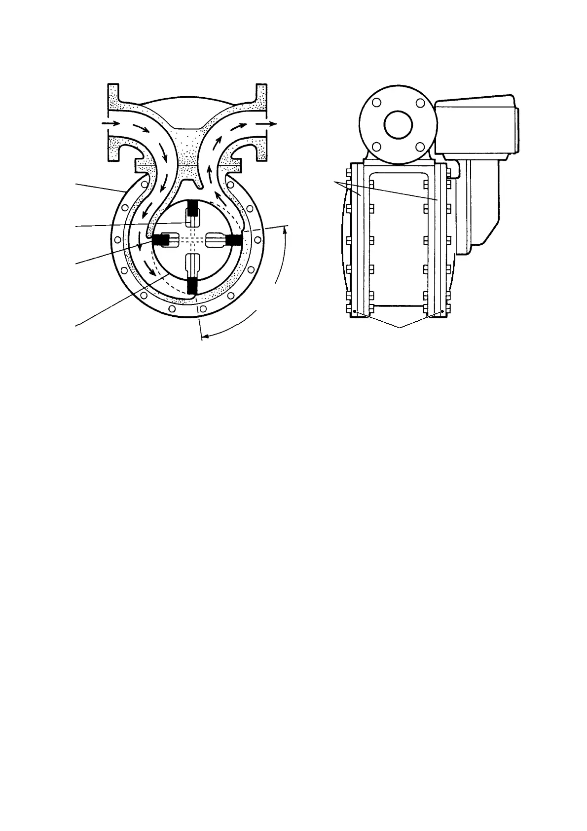
FIG 1.2 METER OPERATION ( RIGHT HAND DISCHARGE SHOWN)
INLET
INNER
COVERS
CASING
VANE
ROTOR
MEASURING
CRESCENT
ROD
S13610
OUTER
COVERS
1.10 The Bulkmeter produces an output on the rotor shaft proportional to flow. The shaft passes through
the end cover without gearing and all moving parts are constantly immersed in fluid.
1.11 There are several ways of using this output:
• A Mechanical Counter driven through a calibrating mechanism to record batch quantity
and totaliser.
• A Pulse Transmitter mounted directly to the output to relay flow to an electronic
counter and display system, such as Masterload.
1.12 Using a Mechanical Counter, display is available in: Litres, Decalitres, Litres x 10, Imperial gallons,
US gallons and Cubic Metres.
1.13 For further information on the Masterload System and other equipment, please refer to Technical
Manuals TP0025 (Vehicle) and TP0027 (Gantry).
1.14 Accessories that may be fitted to the Bulkmeters are:
• Mechanical Counters, (also with integral electronic pulser output).
• Mechanical Ticket Printers.
• Mechanical Preset Counter with mechanical and electrical switch output.
• Mechanical Preset Valves.
• Electrically Operated Preset/Control Valves.
• Pulse Transmitter.
• Extended Counter Drive and Swivel.
 Loading...