TP0003B
BM METER
Chap 2
Page 4
TECHNICAL DESCRIPTION
Products suitable for use with FLUOROCARBON SEALS
Motor spirit
Aviation gasolines (ie. AVGAS)
Kerosene (with additives)
4.2
The above is only a guide and may not be accurate in every case, especially where extreme
temperatures are concerned. If in any doubt about seal selection, please contact our Engineering
Department at Liquid Controls.
5 ROTOR ASSEMBLY
5.1 The rotor assembly comprises an aluminium or NI-resist cast iron rotor secured by screws to
stainless steel stub axles running in bearings mounted in the inner covers. The output spindle is
located into the front stub axle and secured by a taper pin.
5.2 Slots in the rotor accept two pairs of horizontally opposed carbon vanes set at 90 degrees to each
other and mounted on rigid stainless steel rods. The rods are sealed with special glands where they
pass through the rotor.
5.3 In operation, liquid enters the meter through the inlet manifold and causes the rotor to revolve by
pressure on the vanes. The proximity of the rotor to the casing forms an efficient seal, whilst the
profile of the casing ensures that the vanes are guided through the metering crescent, where the
volume of product is accurately measured. Product at line pressure fills the spaces between the
inner and outer end covers providing pressure balanced inner end covers free from distortion. The
rotor motion is transmitted through an output spindle (which passes through a pressure tight seal in
the outer front cover) to the calibrating mechanism which, in turn, drives the mechanical counter.
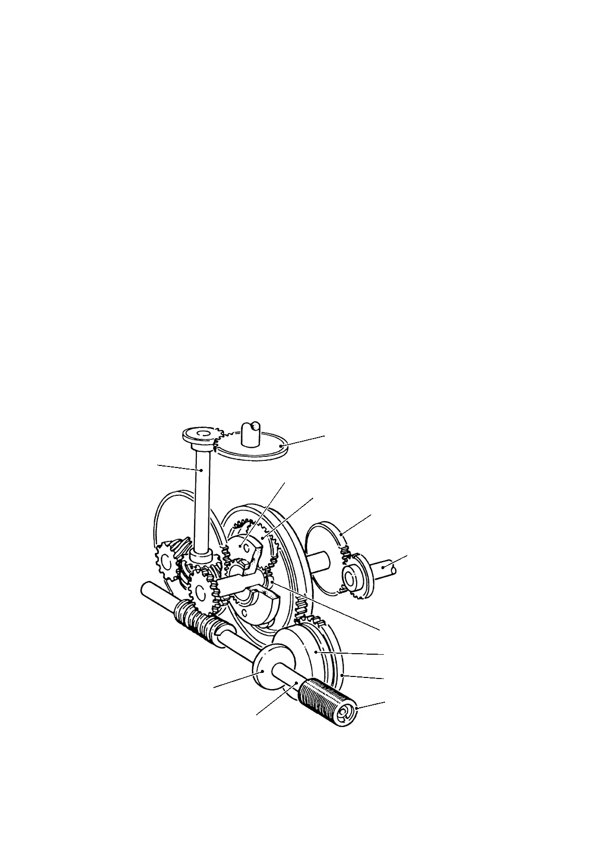
6 CALIBRATING MECHANISM
FIG 2.3 calibrating mechanism GEAR ARRANGEMENT
INTERMEDIATE
SHAFT
REGISTER
DRIVE
PLANET GEAR CARRIER
PLANET GEAR
INPUT GEAR OF CALIBRATING
MECHANISM
OUTPUT SHAFT
OF BULKMETER
SUN GEAR
FRICTION DISC
DISC GEAR
CALIBRATING SCREW
FRICTION ROLLER
WORM SHAFT
S14018
 Loading...