TP0003B
BM BULKMETER
Chap 8
Page 2
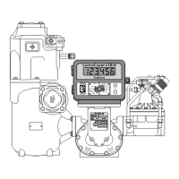
RATE OF FLOW INDICATOR
4 MAINTENANCE
4.1 The maintenance frequencies recommended are a minimum, however, local company instructions
must be observed.
4.2 Daily
Carefully inspect the Rate of Flow Indicator for security and signs of damage. Defects should be
rectified immediately.
4.3 Six Monthly
Check the Indicator for accuracy. Adjust the control valves to a given rate of flow, as displayed on the
indicator, and compare it with the quantity registered on the counter over one minute.
NOTES
1. Rate of flow indicators should only be removed from the bulkmeter for maintenance if the
variation in accuracy falls below acceptable limits viz. +/- 5% FSD.
2. It is recommended that no ’on-site’ dismantling or overhaul of the actual instrument is
attempted, and that faulty indicators be replaced.
5 SERVICING
WARNING
THE RATE OF FLOW IS A DELICATE INSTRUMENT AND CARE MUST BE TAKEN TO ENSURE
THAT THE INDICATOR SHAFT IS NOT PUSHED INTO THE CASE WHEN FITTING THE GEARS
The only servicing procedures necessary are those required to change a defective instrument.
5.1 Removal
For Mk. 2 calibrating mechanisms proceed as follows:
5.1.1 Refer to Fig 7.2 Remove the screws and release the front cover (51), taking care to ensure clean
disengagement of the gears. Discard the cover gasket (57).
5.1.2 Refer to Fig 8.1 Slacken the gear bracket clamping screw (2), remove the gear bracket and gear
assembly from the rear of the indicator (1).
5.1.3 Remove the serial number plate.
5.2 Assembly
5.2.1 Fit the serial number plate.
5.2.2 Refer to Fig 8.1. Fit the gear bracket and gear assembly to the rear of the indicator and ’nip’ the gear
bracket clamping screw (2) - do not fully tighten at this stage.
5.2.3 Refer to Fig 7.2. Fit a new cover gasket (57) and assemble the front cover (51) to the calibrating
mechanism, ensuring clean engagement of the gears.
5.3 Adjustment
5.3.1 With the Veeder Root counter removed, slacken the gear bracket clamping screw (2). Move the gear
bracket (3) along the barrel of the indicator to position the compound gear (7) centrally on the
calibrating mechanism friction disc gear, and rotate the gear bracket to ensure correct meshing.
5.3.2 Finally, fully tighten the gear bracket clamping screw (2).
 Loading...