91
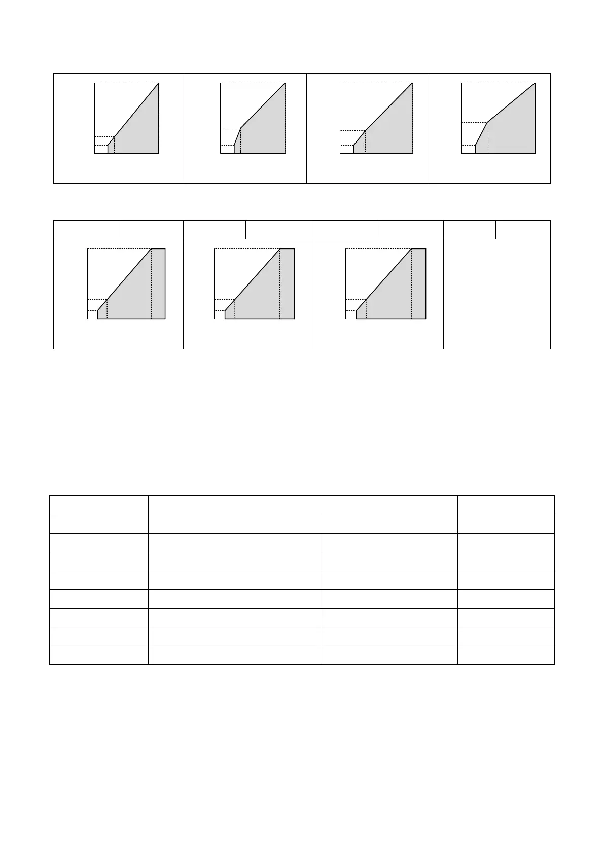
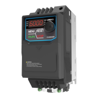
Table 6.17 Fixed Output Characteristics (Setting C to F)
User-Defined V/F Patterns (Default : F)
When d1-01 = F, d1-02 to d1-11 can be set to create a new pattern. d1-02 to d1-11 will be
same as V/F pattern setting 1 after reset.
■ V/F Pattern Settings d1- 02 to d1- 09
When d1-01 ≤ E, the user can use d1-02 to d1-09 to monitor the V/F pattern settings. When
d1-01 = F, d1-02 to d1-09 can be set to create a new pattern as shown in Figure 6.42.
<1> The default setting is determined by A1-02 (Control Method Selection). The settings in this table are the
default in Open-Loop V/F Control.
<2>This is the value for a 200 V AC drive. The value for a 400 V AC drive is doubled.
<3>This will be automatically changed in Auto-Tuning (rotational, stationary 1 or 2).
<4> d1-10 and d1-11 will be disabled when setting 0.0.