Operating Manual
Tangential Rolling System T18F - T27F
10
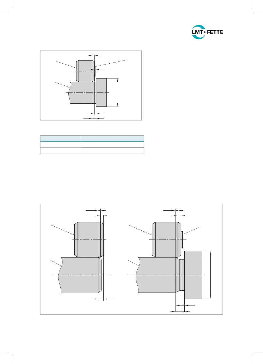
If the geometrical proportions
are unfavorable – especially if the
shoulder diameter D
B
is very large in
proportion to the thread – it will still
be necessary to add the width c
1
of
the bearing washer (3) to the safety
distance. This will result in the maxi-
mum distance of the thread from
the shoulder:
a
1
= b + c(+c
1
) = P + 0.5 · P(+c
1
) =
1.5 · P(+c
1
) [mm]
Figure 1: Distance of the thread roll from the shoulder
At the free end of the thread or the
workpiece tip, the leading edge of
the thread roll (1) must ideally be
located at the dimension
b + P = 2 · P before the start of the thread (see Figure 2-left). If this dimension is not
achieved it may result in a significant tool life reduction of the thread roll.
The same applies also to a thread undercut (see Figure 2-right). The dimension
b + P must be maintained. The correct safety distance c is automatically achieved if
the length g
2
of the thread undercut is as per DIN 76-A. The length is then approx.
g
2
≈ 3.5 · P.
1
2
1 x P
b
b + P
1
3
2
1 x P
b
≥ c
g
2
D
B
Figure 2: Thread roll at the free end and thread undercut
Rolling head type Width of bearing washer c
1
T18F 0.6 mm l 0.0236 inch
T27F 0.8 mm l 0.0314 inch
b
1
2
3
a
1
c
c
1
D
B
LMT_Bedienungsanleitung_T18F_T27F_e.indd 10 02.08.11 17:40
 Loading...