Operating Manual
Tangential Rolling System T18F - T27F
19
5 Assembly and installation
5.1 Preparing the rolling head
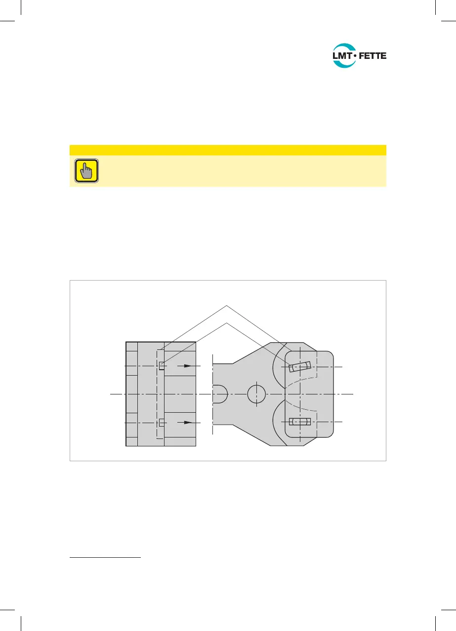
5.1.1 Checking the gear settings
ATTENTION
Check that the rolling head is working properly prior to initial operation!
The thread rolls are synchronized via a gear unit. The synchronous operation of the
gear unit must be checked after assembly.
For this, loosen the cap screw (ET-25)
1
Pull out the pins (ET-3) in the direction of the
arrow. Remove the rolls (ET-18) if necessary. The driving claws of the pinion (ET-8)
must be able to engage in the steel reference gage (ET-36) (see Figure 8). It may be
necessary to adjust the distance between the axes (see Chapter 5.1.5).
1
2
ET-36
ET-8
Figure 8: Checking the gear settings
If the driving claws are not aligned correctly with one another, the gear unit will have
to be synchronized. For this, loosen the set screw (ET-27), pull out the bushing (ET-4)
from the hinge.
1
For part numbers with the addition “SP” see the spare parts list Figure 24 on page 48.
LMT_Bedienungsanleitung_T18F_T27F_e.indd 19 02.08.11 17:40
 Loading...