Operating Manual
Tangential Rolling System T18F - T27F
24
ATTENTION
The determined blank diameter must be maintained with a tolerance of
± 0.015 mm l 0.0005 inch!
The chamfer angle should be γ = 10 … 30°. The inner diameter d
i
should be below the
thread core diameter d
3
:
d
i
≤ d
3
– 0.1 mm [mm]
d
i
≤ d
3
– 0.004 inch [inch]
A chamfer angle γ = 30° produces a chamfer of approx. 45° after rolling on the work-
piece.
NOTICE
Larger chamfers significantly reduce the tool life of the thread rolls.
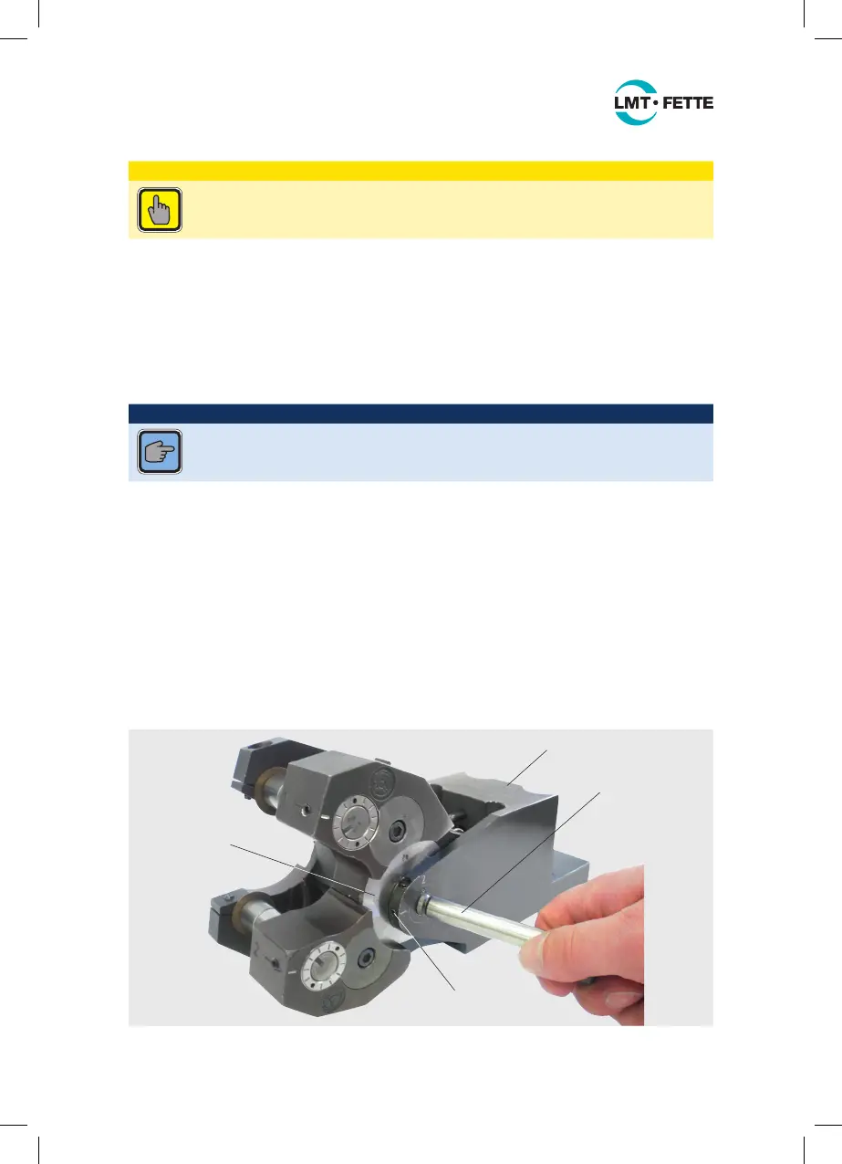
5.2.2 Placing the rolling head into the holder
Install the rolling head holder on the machine tool. Insert the tangential rolling head
into the rolling head holder. To do this, proceed as follows (see also Figure 14):
■ Loosen the set screws (ET-31-12) on the rolling head holder
■ Pull the axis (ET-31-4) sideways out of the rolling head holder
■ Slide the rolling head between the two brackets of the holder and insert the axis
(ET-31-4) through the rolling head holder and through the rolling head on the bush-
ing (ET-4)
■ Check whether the rolling head can pivot freely about the holder axis
■ Retighten the set screws (ET-31-12)
ET-31
ET-31-4
ET-4
ET-31-12
Figure 14: Setting the rolling head in the holder
LMT_Bedienungsanleitung_T18F_T27F_e.indd 24 02.08.11 17:40