Operating Manual
Tangential Rolling System T18F - T27F
30
6.3 Traverse paths
A
S
A
S
n
w
n
D
A
V
A
V
> 0
3
S
1
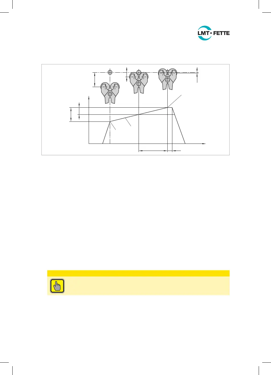
Figure 17: Traverse paths
The tangential rolling head is moved sideways against the rotating workpiece.
Figure17 contains a schematic representation of the traverse path of the tangential
rolling head:
1. The tangential rolling head is rapidly moved to position 1. This is located in the
safety distance A
s
in front of the workpiece axis. A
s
is calculated from A
v
(see setting gauge or Internet) plus 50 % · A
v
:
A
s
= A
v
+ 50 % · A
v
= 1.5 · A
v
[mm]
This value results in an X-coordinate D
s
(with reference to the diameter) in a CNC program of:
D
s
= 2 ·
(
d
A
___
2
+ 1.5 · A
v
)
= 2 ·
(
d
A
___
2
+ A
s
)
[mm]
2. From position 1, the head is moved in working feed (see above) s or f up to position 3.
ATTENTION
Make sure that the thread rolls are never moved beyond the center
of the workpiece.
Ensure that position 3 is correct using the suitable setting gauge for the tangential
rolling head and the thread rolls via the F-gauge (see Figure 18):
■ For this, mount the rolling head holder (3) on the machine tool
■ Insert the setting gauge (2), instead of the tangential rolling head, into the rolling
head holder by sliding the setting gauge in the rolling head holder on the bolt
(ET-31-4). Clamp the bolt with the set screw (ET-31-12).
LMT_Bedienungsanleitung_T18F_T27F_e.indd 30 02.08.11 17:40