Operating Manual
Tangential Rolling System T18F - T27F
21
bore(8). Insert the bushings (ET-1)
2
into the thread rolls. Slide the roll marked with
number “1” onto the hinge side on the pinion claw (ET-8) marked with number 1, mak-
ing sure that number “1” on the roll is facing towards the workpiece (4), (see Figure 9).
Also apply a coat of molybdenum sulfide grease to the axis (ET-3) and insert it from
the gear unit side (5) into the thread roll hole. Slide the washer (ET-15) between the
roll and the narrow rolling head arm side. Slide the axis up to the end stop. In the 0
position, the slot (7) on the axis – viewed from the gear unit arm side – must be aligned
with the line (6) on the gear unit arm. Firmly clamp the axis with the cap screw (ET-25).
Proceed in the same way to mount thread roll 2.
NOTICE
After thread roll number 1 has been mounted make sure that it is no longer
rotated. Ensure that both numbers are facing towards the workpiece, see
Figure 9.
ATTENTION
To ensure a good frictional behavior between the roll and the carbide axis, it
is essential to apply a coat of molybdenum sulfide grease (e. g. Molykote) to
the roll hole and the carbide axis in the region of the roll and the pinion!
5.1.3 Adjusting the roll movement, axial direction
After the thread rolls have been mounted the axial rolling clearance is adjusted.
Controlling the axial rolling clearance is especially important in the case of fine
threads. With very fine thread pitches P there is a risk of chip formation during the
rolling process. If the clearance becomes greater than 0.1 mm l 0.004 inch (in the case
of fine thread pitches greater than 0.05 mm l 0.002 inch) the fine setting has to be
adjusted. The washer (ET-15) also has to be checked and replaced if excessively worn.
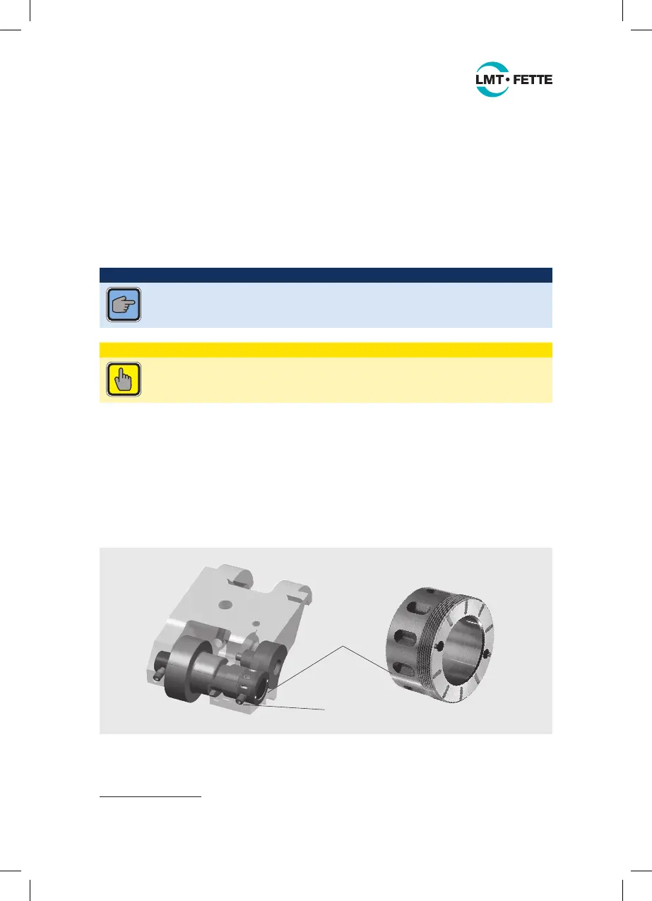
ET-13
ET-37
Figure 10: Adjusting the axial clearance
2
For part numbers with the addition “SP” see the spare parts list Figure 24 on page 48.
LMT_Bedienungsanleitung_T18F_T27F_e.indd 21 02.08.11 17:40
 Loading...