Operating Manual
Tangential Rolling System T18F - T27F
32
6.4 Tangential force, drive power and torque
Tangential force
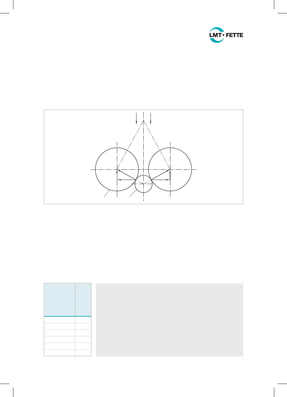
The tangential rolling head is designed to work according to the plunge method. The
two rolls (Figure 19-1) are moved sideways across the workpiece (Figure 19-2), and
the rolling profile enters the workpiece tangentially thus creating the desired form. The
machine is required to produce the tangential force F
T
during this process. The radial
force F
R
is absorbed by the rolling head.
F
T
12
F
T
F
T
F
T
F
R
F
R
Figure 19: Forces exerted during tangential rolling
The force required to roll the profile must be produced by the cross slide or the turret
slide. This is normally not a problem on cam-controlled automatic lathes. On hydraulic
or electric-controlled slides it is necessary to check the tangential force.
The tangential force F
T
is calculated as follows:
F
T
=
2340 · L · K
WT
_____________
n
w
(0.06 · d
0.82
+ 0.46 · P – 0.1 · Z + 1) [N]
The material constant K
WT
results from the following table:
Tensile
strength
R
m
of the
material
[N/mm
2
] K
WT
0 … 500 1
500 … 700 1.2
700 … 900 1.3
> 900 1.4
Copper 1.1
Brass 0.9
Calculation example:
Thread M22 x 2.5
Thread diameter d = 22 mm
Thread pitch P = 2.5 mm
Workpiece RPM n = 480 1/min
Material constant K
WT
= 1.2
Thread length L = 18 mm
Number of workpiece rotations n
w
= 30 (see Chapter 6.2)
Thread starts on roll Z = 3
F
T
=
2340 · 18 · 1.2
_____________
30
(0.06 · 22
0.82
+ 0.46 · 2.5 – 0.1 · 3 + 1)N = 4391.8 N
LMT_Bedienungsanleitung_T18F_T27F_e.indd 32 02.08.11 17:40