Operating Manual
Tangential Rolling System T18F - T27F
12
The width dimensions B
1
… B
6
of the rolling head are specified in Chapter 12.1. Note
that the rolling head can also be rotated in the holder. That is, either the narrow arm
side B
3
or the wide arm side B
4
may be facing towards the workpiece clamping.
The maximum shoulder diameters D
BK
, D
BG
and D
BR
at the workpiece are dependent
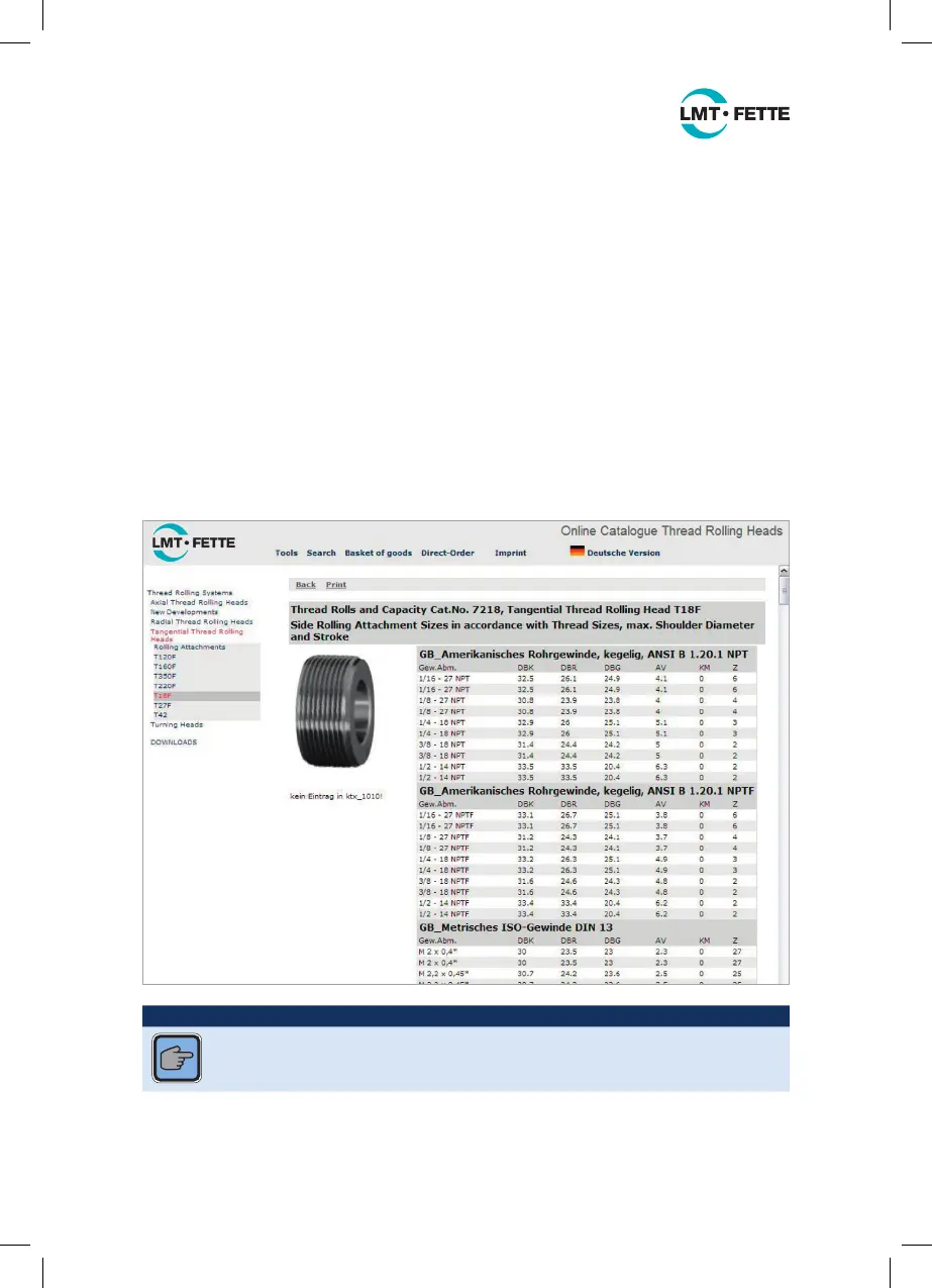
on the respective thread size. The values are specified in table form online at
www.fette.de/rk/fettekat.
Abbreviations used in the following table (excerpt only):
D
BK
= Max. shoulder diameter under the narrow (“short”) arm side of the rolling head
D
BR
= Max. shoulder diameter under a recessed thread roll
D
BG
= Max. shoulder diameter under the wide (“drive”) arm side of the rolling head
A
v
= Theoretical working stroke of the rolling head (see Chapter 4.4 and 6.3)
Z = Number of starts on the roll (see Chapter 4.4)
Table 3: Shoulder diameter and operation data (excerpt from the Internet)
NOTICE
With tapered threads (metric and Whitworth profiles) the shoulder diameter
and working strokes with parallel threads of the same dimensions are
identical.
Each rolling head size can be used for the complete working range; only the rolls and
the setting gauge need to be adapted to the individual work applications.
LMT_Bedienungsanleitung_T18F_T27F_e.indd 12 02.08.11 17:40
 Loading...