DYNAMIC MOTION SYSTEM - CONFIGURATION HANDBOOK // PAGE 10
4 COMPONENT OVERVIEW
This chapter provides an overview of LOGICDATA products that are either part of the DYNAMIC MOTION
system, or are compatible with it. Not all products can be used in the same system. Some of the listed prod-
ucts do not belong to congurations currently approved by LOGICDATA, but may be planned for future sys-
tems. Always read the Operating Manual of each product in the system before assembly and operation.
4.1 ACTUATORS
4.1.1 WHAT IS AN ACTUATOR?
Actuators take power from the Power Unit in order to rotate a spindle that moves the table up or down. There
are two main categories of Actuator in the DYNAMIC MOTION system: Drives (in which the spindle is per-
manently attached to the motor) and Gear Motors (no spindle attached). DYNAMIC MOTION actuators also
feature an integrated Control Unit.
4.1.2 TYPES OF ACTUATOR
Name and Order Code Key Features Image
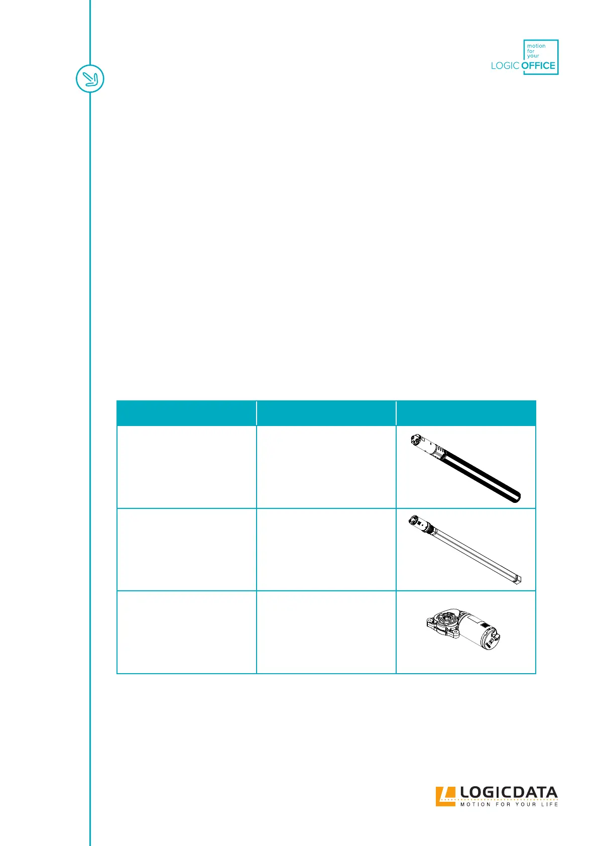
DMD660
DMD660-a-b
• Installation length: 511 mm /
20.14 ”
• Stroke: 662 mm / 26.04 ”
• Application: Dual-stage
Height-Adjustable Columns
DMD500
DMD500-a-b
• Installation length: 606 mm /
23.84 ”
• Stroke: 497 mm / 19.57 ”
• Application: Single-stage
Height-Adjustable Columns
DMG90
DMG90-a-b
• Motor Diameter: 40 mm / 1.57 ”
• Length: 119.4 mm / 4.691 "
• Application: External spindle
systems