DYNAMIC MOTION SYSTEM - CONFIGURATION HANDBOOK // PAGE 16
5.2.2 TECHNICAL REQUIREMENTS
Before assembling the Table System, ensure the following requirements are met:
• All Actuators have been mounted properly into the Height-Adjustable Columns
• The Height-Adjustable Columns have been mounted correctly onto the Table Top
• The DYNAMIC MOTION system will be connected at a voltage compliant with the Type Plate
• There is no residual voltage on any parts
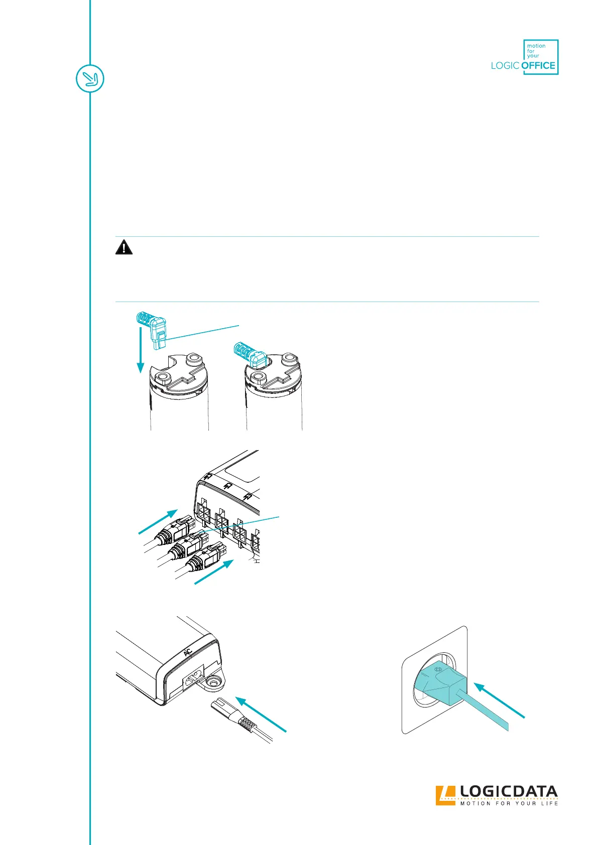
5.3 CONNECTING CABLES
CAUTION
Risk of minor or moderate injury through burns or electric shocks
Connecting Cables to the Power Hub incorrectly may lead to minor or moderate injury
through burns (due to overheating), or electric shocks.
• Do not force or bend Connectors
• Ensure Connectors are oriented correctly (see diagram)
• Do not insert ngers or objects into the Connectors or housing of the Power Hub
Fig. 1: Connecting cables to an Actuator:
Fig. 2: Connecting cables to the Power Hub (or DYNAMIC MOTION Standard Connector)
Fig. 3: Connecting the Power Cable
Locking Tab facing inwards
Locking Tab facing upwards
Do not connect cables while the
system is connected to the mains.