EasyManuals Logo

LOGICDATA DYNAMIC MOTION Configuration Handbook

LOGICDATA DYNAMIC MOTION
23 pages
To Next Page IconTo Next Page
To Previous Page IconTo Previous Page
Page #17 background imageLoading...
Page #17 background image
DYNAMIC MOTION SYSTEM - CONFIGURATION HANDBOOK // PAGE 17
5.4 APPROVED STANDARD TABLE SYSTEMS
This chapter describes assembly for Standard Table Systems (see Chapter 5.1).
5.4.1 STANDARD APPLICATION 1
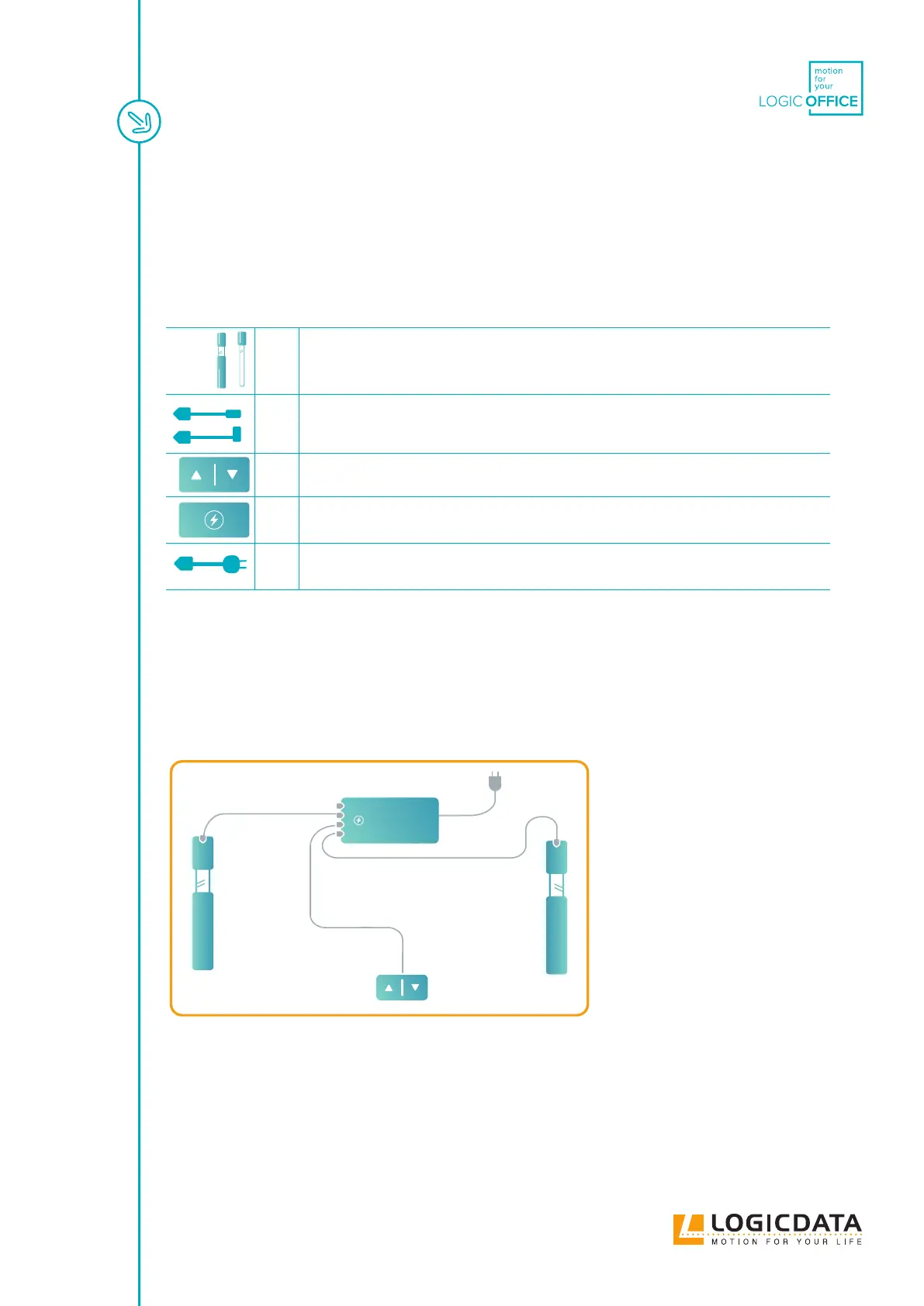
This system creates: 2-leg table with a single Power Hub (DMP240)
2 Height-Adjustable Columns with DMD500 or DMD660 Actuators
2 DMLIN Actuator Cable per Actuator
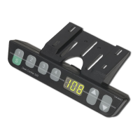
1 User Interface
1 DMP240
1 Power Cable
Connecting the System
1. Plug the Actuator(s) into the Power Hub
2. Plug the User Interface into the Power Hub
3. Plug the Power Hub into the Mains
Fig. 4: Standard Application 1
DMP240

Other manuals for LOGICDATA DYNAMIC MOTION

Questions and Answers:

Question and Answer IconNeed help?

Do you have a question about the LOGICDATA DYNAMIC MOTION and is the answer not in the manual?

LOGICDATA DYNAMIC MOTION Specifications

General IconGeneral
BrandLOGICDATA
ModelDYNAMIC MOTION
CategoryIndoor Furnishing
LanguageEnglish

Related product manuals