DYNAMIC MOTION SYSTEM - CONFIGURATION HANDBOOK // PAGE 14
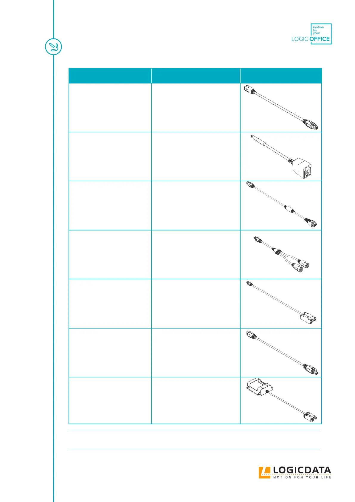
Name and Order Code Key Features Image
Extension Cable
DMLIN-EXT-1000
• Length: 1000 mm
• Connector A: 1 x 4-pin
• Connector B: 1 x 4-pin
• Application: Extension Cable
Sensor Adapter Cable
DMLIN-DMS-100
• Length: 100 mm
• Connector A: 3-pin
• Connector B: 4-pin
• Application: DMS Sensor Adapter
Cable
LOGIClink to DM Cable
DMLIN-LL-1800
• Length: 1800 mm
• Connector A: 1 x 4-pin
• Connector B: 1 x 10-pin
• Application: Power Hub to
Connectivity Hub
Branch Cable
DMC-BR-200
• Length: 200 mm
• Connector A: 1 x 4-pin
• Connector B: 2 x 4-pin
• Application: Branch Cable
Benching Adapter
DMC-BA-2500
• Length: 2500 mm
• Connector A: 1 x 4-pin
• Connector B: 4x 4-pin
• Application:
Benching Application
Cable
Sync Cable
DMC-CA-1000
• Length: 1000 mm
• Connector A: 1 x 4-pin
• Connector B: 1 x 4-pin
• Application: Conference
Application Cable
LOGICcell to DM Cable
DMC-LC-1200
• Length: 1200 mm
• Connector A: 1 x 10-pin
• Connector B: 4x 4-pin
• Application: Adapter Cable for
Battery Packs
NOTICE
Do not connect extension cables to each other to form "extension chains". This may
damage the system.