43
THIS MANUAL IS PROPRIETY OF ECOWIND by LOMBARDINI - ALL FORMS OF REPRODUCTION, PARTIAL OR OTHERWISE, IS STRICTLY PROHIBITED
G
B
Fig. 73
Fig. 75Fig. 74
Fig. 76
G
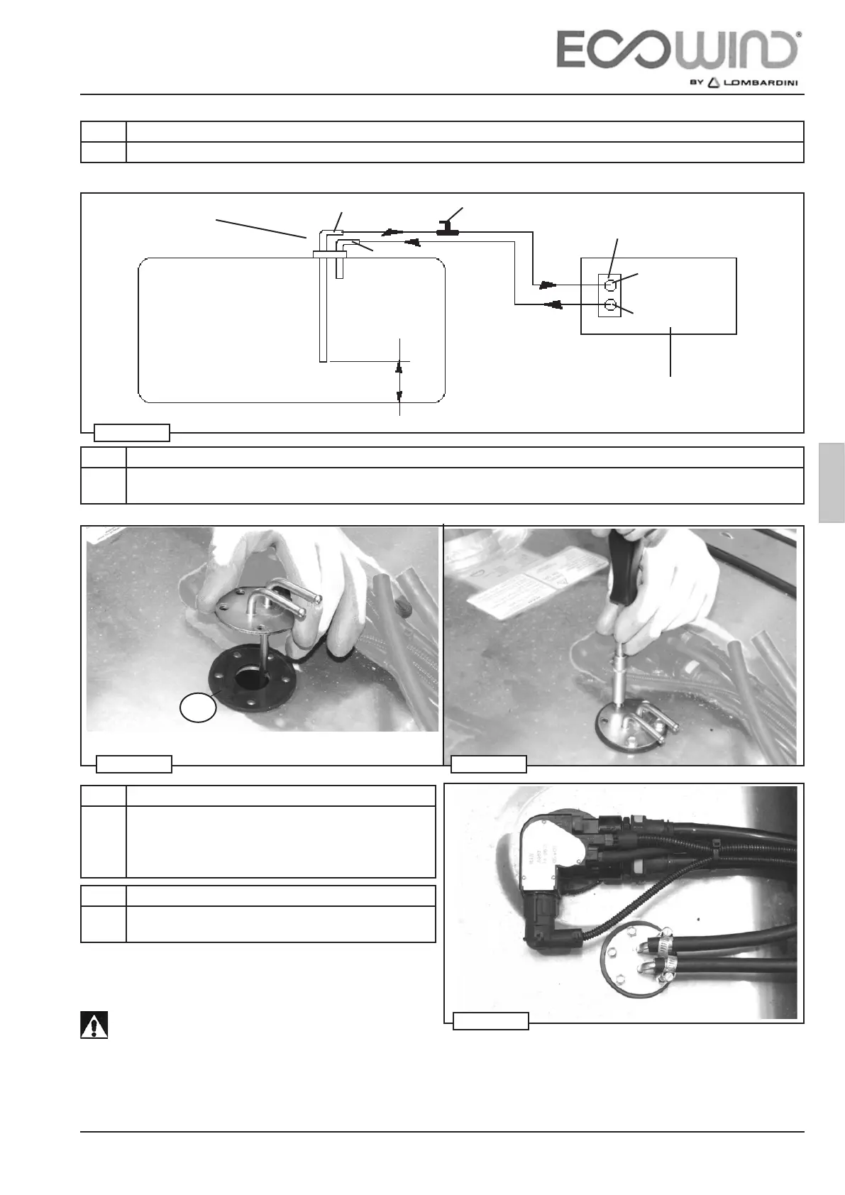
min 100 mm
ATTENTION! ! !
The fuel intake pipe (IN) of the suction pipe (P) must be connected to the safety cock (R) (g. 73)
and to the coupling IN on the Power Unit.
NON-OBSERVANCE OF THIS STEP COULD PREVENT THE SYSTEM FROM FUNCTIONING! ! !
3 - ASSEMBLY AND INSTALLATION
Suction pipe (P)
Tank (S)
Step Description
4 Cut the metal suction pipe to the appropriate size as in gure 73.
Step Description
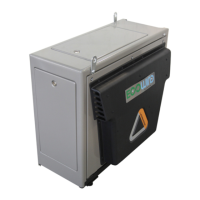
5 Attach the suction pipe P to the tank S using the supplied self-threading screws, placing the rubber gasket G between
the two (g. 74-75).
Step Description
6
*
For tank with cylindrical shape, we suggest to use 2
rubber gaskets G g 70
Step Description
7 Connect the suction pipe P to the Power Unit PW, via
the supplied rubber hose and metal clamps (g. 76).
IN
OUT
OUT
IN
FUEL
Panel Power Unit
ON/OFF cock