38
THIS MANUAL IS PROPRIETY OF ECOWIND by LOMBARDINI - ALL FORMS OF REPRODUCTION, PARTIAL OR OTHERWISE, IS STRICTLY PROHIBITED
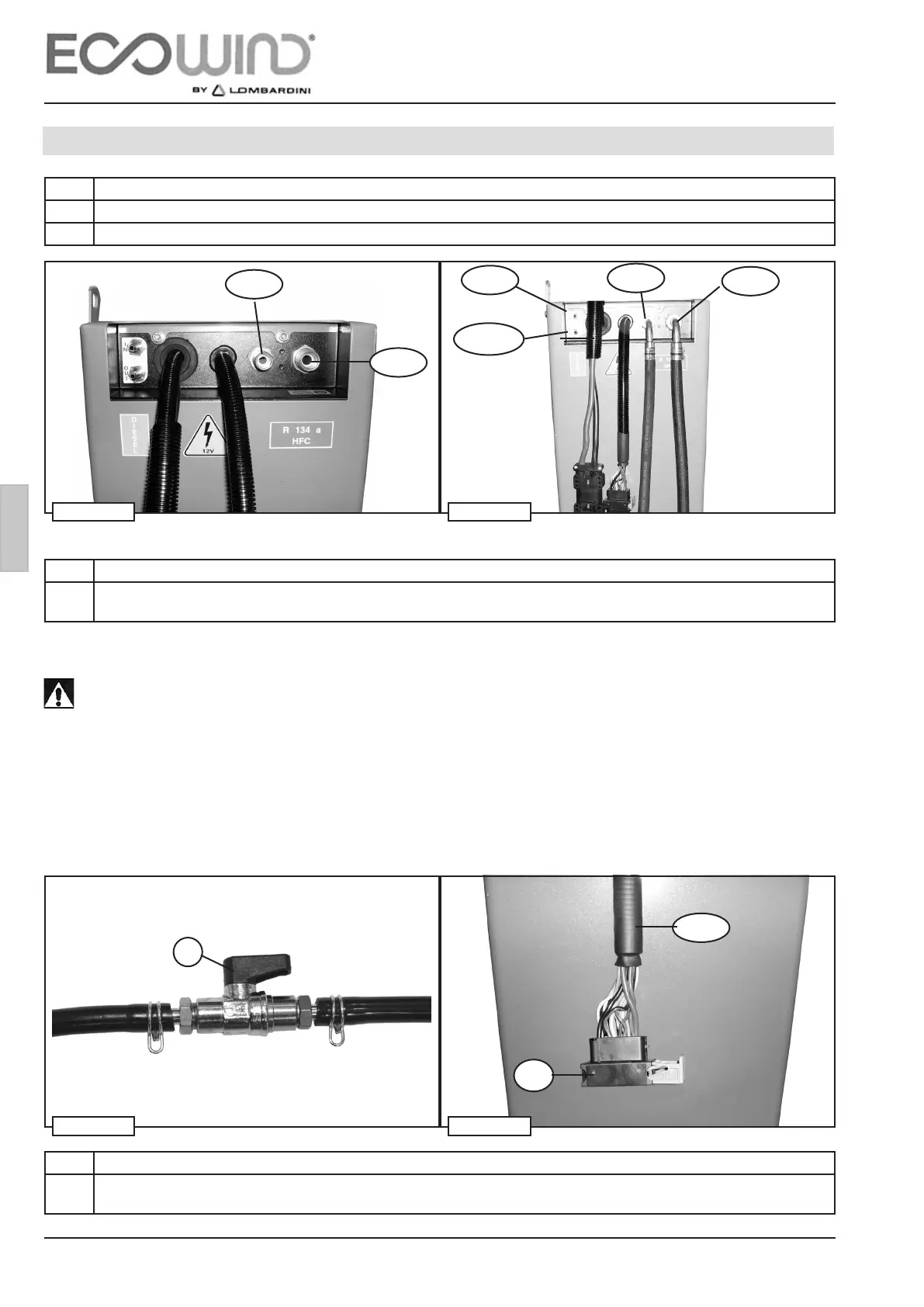
G
B
Tg In
Tg Out
R
G 8
G 8
G 10
Fc
G 10
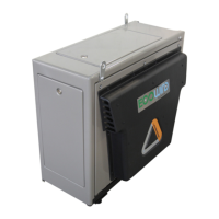
2c
Fig. 64Fig. 63
Fig. 62Fig. 61
ATTENTION! ! !
The diesel fuel on/off cock “R” (supplied), which is a system safety device, must be connected to
the diesel fuel pipe “IN” (g. 63), see also g. 73 pag. 41.
Lombardini declines all responsibility for damage caused as a result of non-observance of the
safety system.
Step Description
4 The connector bundle 2c (g. 64) must be connected to the respective FRAMATOME 3c connectors of the extension
P supplied g. 66.
Step Description
3 Both diesel fuel couplings Tg in – Tg out must be connected by means of the supplied Ø 5 rubber hose to the corre-
sponding couplings on the diesel fuel suction pipe (see g. 73 on page 41) and clamps supplied.
Step Description
1 Connect the gas delivery pipe G8 (g. 62) to the Power Unit using a 90° union supplied.
2 Connect the gas suction pipe G10 (g. 62) to the Power Unit using a 90° union supplied.
ASSEMBLY AND INSTALLATION - 3
3.7 HOSES AND CABLES CONNECTIONS TO POWER UNIT