Pc-Boards
- 17 -02.20 909.2710.1-06
DIP switch
It is possible to program the DSP (Process) via a serial port (RS232 at connector X23). To set the proces-
sor into programming mode, the DIP switches 1, 2 and 3 must be set to “ON”. All details about the serial
programming is given in the operating manual “LorchInstall” (909.0410.1).
The DIP switch 4 is used to set the configuration of the water cooling unit. It is set due to the type of the
unit (external or internal watercooling).
DIP switch setting “ON” setting “OFF”
1, 2, 3 DSP programming mode active normal mode
4 configuration external cooling unit (WUK)
for S3 mobile / P3000 mobile
configuration internal cooling unit
for S3, S5, S8 / P3500, P4500, P5500
Tab. 4: Settings DIP switches
Measuringpoints
designation
measuring
point
result
supply voltage from control transformer (primary) X6-1
X6-3
~
~
230V AC (driveable housing)
42V AC (S mobile/ P mobile)
supply voltage fans group 1 X7-1
X7-2
~
~
230V AC
supply voltage fans group 2 X25-1
X25-2
~
~
230V AC
supply voltage cooling unit X13-1
X13-2
~
~
230V AC
supply voltage from control transformer (secondary) X2-1
X2-2
~
~
18V AC
X2-3
X2-4
~
~
42V AC
supply voltage flow meter X9-1
X9-3
+
gnd
+15V DC
supply voltage LorchNet
(CAN bus)
X8-1
X8-2
gnd
+
+15V DC
X14-1
X14-2
gnd
+
+15V DC
X20-1
X20-2
gnd
+
+15V DC
Tab. 5: Measuringpoints MAPRO05
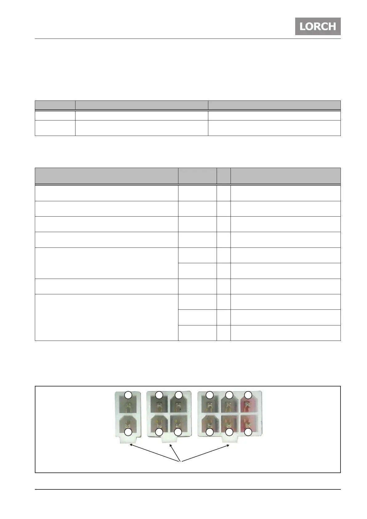
Counting pins for Minifit and Microfit connectors
The way of reading the pin numbers on the Minifit- and Microfit-connectors is done always in the same
way: when looking from the top onto the connector, pin no.1 is alway on the far left, opposite to the clip
Clip
654
32121
43
1
2
Fig. 7: Reading connector pin numbers