Doc: I500GBPL07_19 2020-02-03 p. 25 / 38
TC J
TC K
P22.n.02 Początek wartości skali 0 -9999 - +9999
P22.n.03 Mnożni
x1 /100
x1k
P22.n.04 Koniec wartości skali 100 -9999 - +9999
P22.n.05 Mnożni
x1 /100
x1k
P22.n.06 Opis
INn (Tekst
16
znaków)
P22.n.07 Jednostka pomiaru UdM (Tekst
6 znaków)
Uwaga: to menu zostało podzielone na 4 części, każda dla 1 wejścia analogowego
AIN1…AIN4,
dostępnych z modułem rozszerzeń EXP1004T i EXP1041.
P22.n.01 –
Określa typ czujnika podłączonego do wejścia analogowego. Czujnik
powinien być podłączony do właściwego zacisku dla danego typu. Zobacz instrukcję
modułu wejść.
P22.n.02 i P22.n.03 –
Definiują wartość wyświetlaną przy minimalnym sygnale czujnika,
inaczej mówiąc początek skali dla zdefiniowanego typu (0mA, 4mA, 0V, -5V). Uwaga: te
parametry nie są używane dla czujników typu PT100.
P22.n.04 i P22.n.05 –
Definiują wartość wyświetlaną przy maksymalnym sygnale
czujnika, inaczej mówiąc koniec skali dla zdefiniowanego typu (20ma,10V, +5V). Uwaga:
te parametry nie są używane dla czujników typu PT100.
P22.n.06 –
Opis pomiaru przypisanego do wejścia analogowego. 16 dowolnych znaków.
P22.n.07 –
Jednostka pomiaru. 6 dowolnych znaków. Jeśli wejście jest typu PT100 a
tekst jednostki pomiaru to °F, wizualizacja temperatury będzie w stopniach Fahrenheit,
w innym przypadku w stopniach Celsjusza.
TC J
TC K
P22.n.02 Start of scale value 0 -9999 - +9999
P22.n.03 Multiplier x1 /100
x1k
P22.n.04 End of scale value 100 -9999 - +9999
P22.n.05 Multiplier x1 /100
x1k
P22.n.06 Description
INn (Text
16 chars)
P22.n.07 Unit of measurement UoM (Text
6 chars)
Note: this menu is divided into 4 sections for the analog inputs AIN1…AIN4,
available with the EXP1004T and EXP1041 expansion modules.
P22.n.01 – Specifies the type of sensor connected to analog input. The sensor should be
connected to the appropriate terminal for the type selected. See input module manual.
P22.n.02 and P22.n.03 – Define the value to display for a min. sensor signal, in other
words at the start of the range defined by the type (0mA, 4mA, 0V, -5V, etc.). Note: these
parameters aren’t used for a type PT100 sensor.
P22.n.04 and P22.n.05 – Define the value to display for a max. sensor signal, in other
words at the end of scale of the range defined by the type (20ma, 10V, +5V, etc.). These
parameters aren’t used for a type PT100 sensor.
P22.n.06 – Description of measurements associated with analog input. 16-character free
text.
P22.n.07 – Unit of measurement. 6-character free text. If the input is type PT100 and the
text of the unit of measurement is °F, the temperature will be displayed in degrees
Fahrenheit, otherwise it will be in degrees Celsius.
M24 – ALARMY U
YTKOWNIKA
(UAn, n=1…8)
m domyślnie Zakres
P24.n.01 Źródło alarmu OFF OFF
INPx
OUTx
LIMx
REMx
PLCx
RALx
TIMx
P24.n.02 Numer kanału (x) 1 OFF/1…99
P24.n.03 Tekst U
n (Tekst
16
znaków)
Uwaga: to menu zostało podzielone na 8 części, każda dla 1 alarmu użytkownika
UA1…UA8..
P24.n.01 –
Definiuje wejście cyfrowe lub zmienną wewnętrzną, które generują alarm
użytkownika kiedy są aktywowane..
P24.n.02 –
Numer kanału x odnoszący się do poprzedniego parametru.
P24.n.03 –
Dowolny tekst, który pojawia się na ekranie okna alarmowego.
M24 – USER ALARMS
UAn, n=1…8)
UoM Default Range
P24.n.01
larm source OFF OFF
INPx
OUTx
LIMx
REMx
PLCx
RALx
TIMx
P24.n.02 Channel number (x) 1 1-99
P24.n.03 Text UAn (text
16 chars)
Note: this menu is divided into 8 sections fo
user alarms UA1…UA
P39.n.01 – Defines the digital input or internal variable that generates the user alarm
when it is activated.
P39.n.02 – Channel number x with reference to the previous parameter.
P39.n.03 – Free text that appears in the alarm window.
Domyślne ALARMY ZDALNE / STATUS
P20.01.01 Wyłączony tryb automatyczny
P20.02.01 Brak rozruchu
P20.03.01 Dyspozycja uruchomienia
P20.04.01
larm globalny
P20.05.01 Zawór ssący częściowo otwarty
P20.06.01 Częściowo otwarty zawór tłoczny
P20.07.01 Minimalny poziom paliwa
P20.08.01
larm zraszacza pompy lokalnej (na wyświetlaczu:zraszacz
włączony)
P20.09.01
waria pompy drenażowej
P20.10.01
larm niskiej temperatury w pompowni
P20.11.01
waria pompy
ockey
P20.12.01 Wyłączony
P20.13.01 Wyłączony
P20.14.01 Wyłączony
Default
P20.01.01
utomatic mode locked
P20.02.01 Engine start failure
P20.03.01 Engine on cranking
P20.04.01 Global alarm
P20.05.01 Suction valve partially open
P20.06.01 Delivery valve partially open
P20.07.01 Min fuel limit level
P20.08.01 Room pump sprinkler alarm (su display:sprinkler activated)
P20.09.01 Drain pump failure
P20.10.01 Low temperature alarm of room pump
P20.11.01 Jockey pump failure
P20.12.01 Disabled
P20.13.01 Disabled
P20.14.01 Disabled
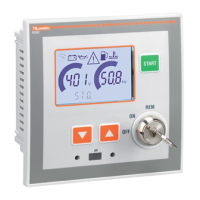
Alarmy
Kiedy generowany jest alarm na wyświetlaczu pojawi się ikona alarmowa, kod
alarmu i opis alarmu w wybranym języku.
Po wciśnięciu przycisków nawigacyjnych okienko z opisem alarmu znika na
chwilę, by pojawić się ponownie po upływie kilku sekund.
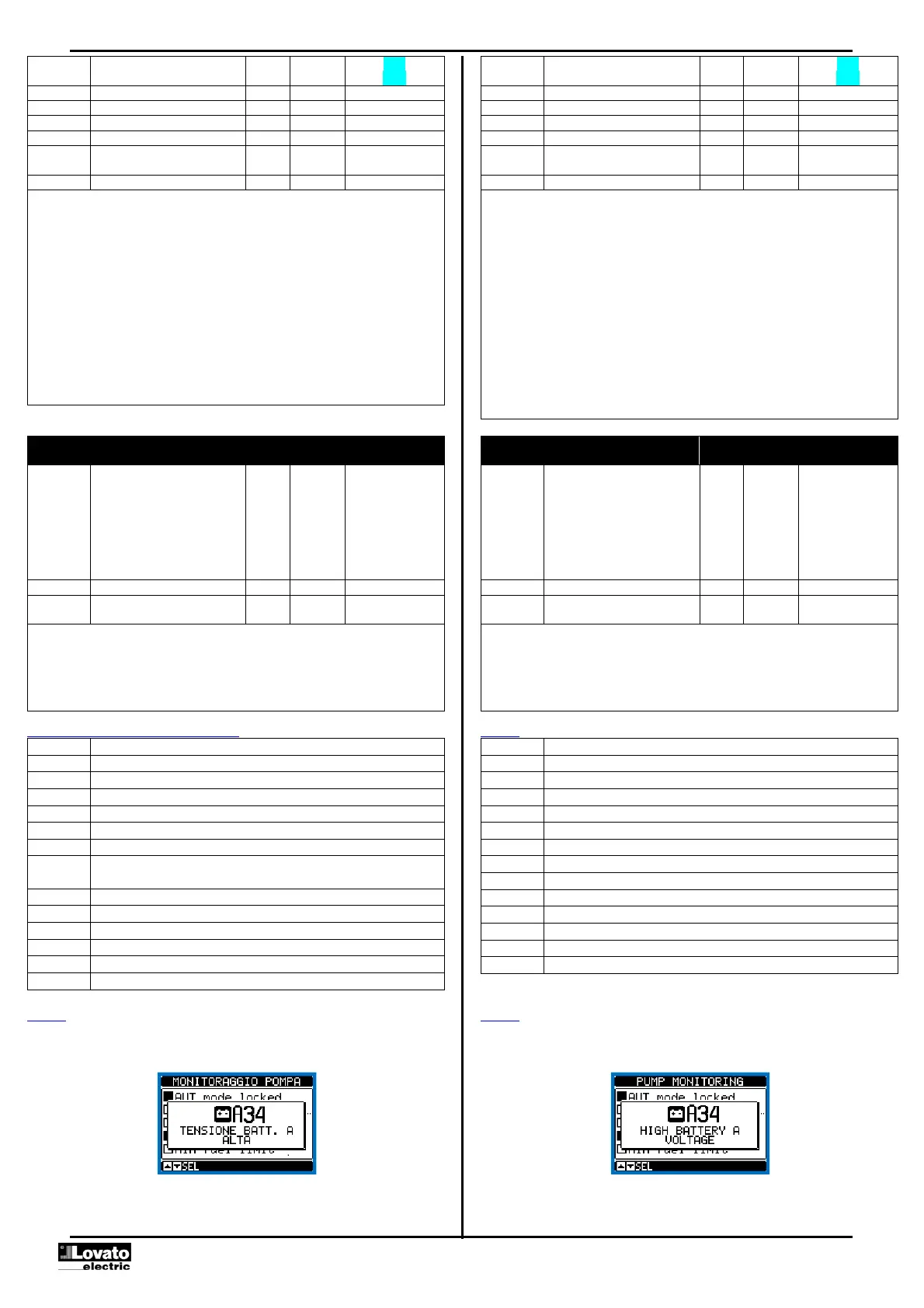
larms
When an alarm is generated, the display will show an alarm icon, the code and
the description of the alarm in the language selected.
If the navigation keys in the pages are pressed, the pop-up window showing
the alarm indications will disappear momentarily, to reappear again after a few
seconds.
 Loading...