en – Original instructions
38
6.6 Technical references
6.6.1
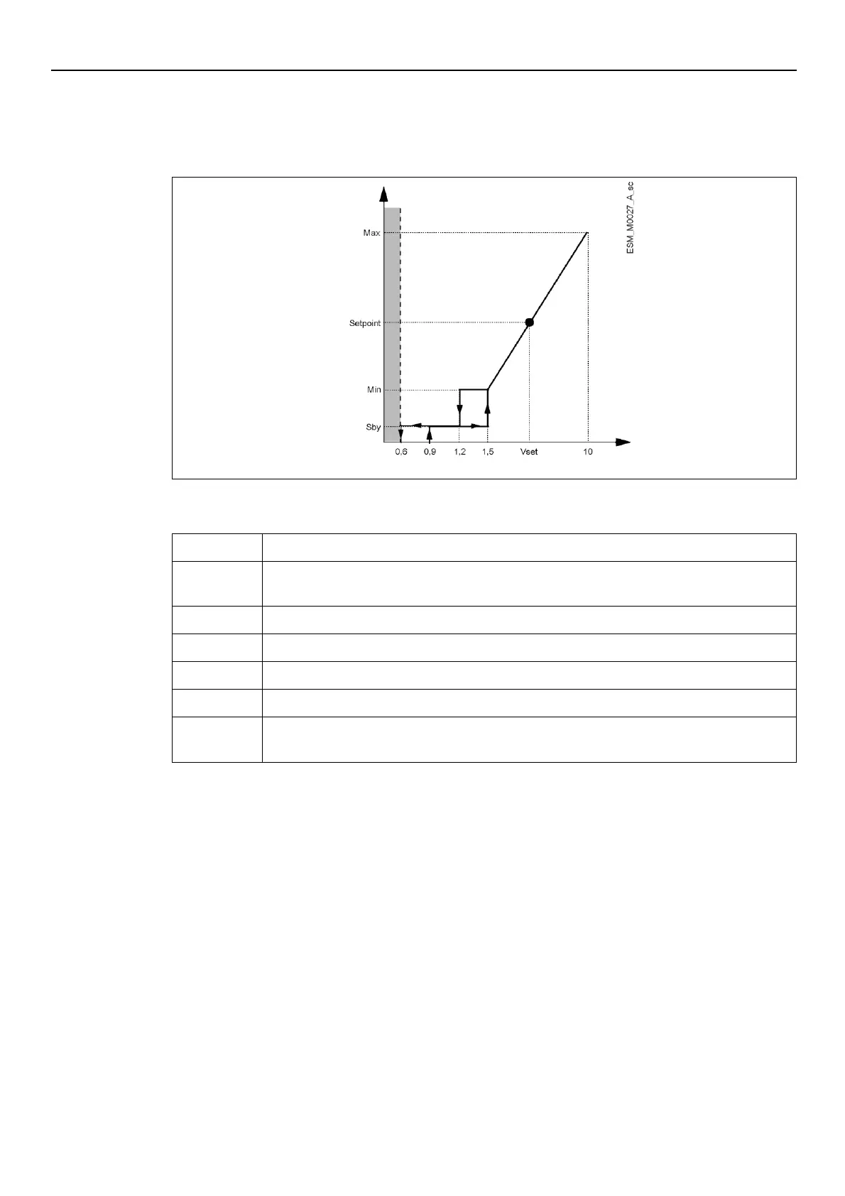
Example: ACT control mode with analog 0-10V input
Graph
Figure 17: ACT control mode diagram
Missing input Voltage detection threshold
Actual speed relative to the 0-10V analogue input voltage value (see Par. 4.3.3, table 8 contacts
7 and 8)
Example of Actual Speed related to a specific Vset Voltage value
Input Voltage at which the motor goes in Stand By
Input Voltage value to control the pump in ACT mode
Different thresholds are managed by the pump, from Non-detection to Max speed)
For further information on the control mode and the ACT regulation parameters, see Par. 6.5.3.



 To Next Page