en – Original instructions
39
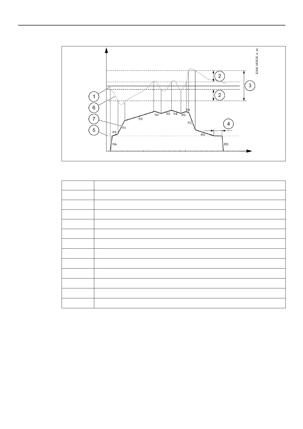
6.6.2 Example: Ramp Settings
Graph
P37 (Adjustment hysteresis) as a % of P36 (Adjustment window)
P36 (Adjustment window) as a % of P01 (Required Value)
P35 (Minimum speed - Duration)
P32 (Acceleration ramp at startup)
P32 (Deceleration ramp at shutdown)
P28 (Ramp 1) - Fast ramp speed increase
P29 (Ramp 2) - Fast ramp speed decrease
P30 (Ramp 3) - Slow ramp speed increase
P31 (Ramp 4) - Slow ramp speed decrease
For further information on the adjustment of the ramps, see Par. 6.5.3.
6.6.3 Example: Effective Required Value
Pumps activation in cascade modes:
1. Lead pump reaches its P60 (Enable Speed).
2. Actual value falls to the cut in-value of the 1st assist pump.
The 1st assist pump switches on automatically. (Cut-in value = P01 (Required Value) - P59
(Actual Value Decrease))
3. A new required value, P02 (Effective Required Value) is calculated after the start up.